person
Finn Harald Sandberg, Norwegian Petroleum Museum
Utilities are a collective term for the systems required to operate a platform, other than those directly involved in oil and gas production. This definition embraces direct support for the production process, general power generation facilities, and systems which sustain life and work on the installation. The latter include safety, process control, heating and ventilation, and communication equipment.
— Cooling water pumps at Statfjord A. Photo: Shadé Barka Martins/Norwegian Petroleum Museum
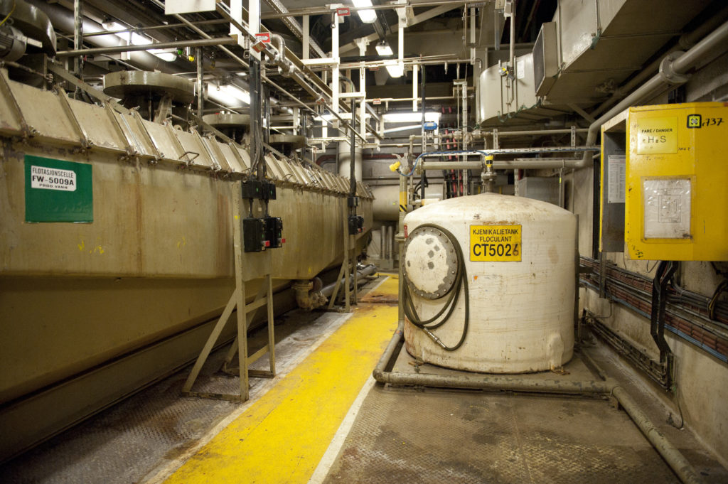
hjelpesystemer, engelsk,Flotation cell and tank for chemicalies on Statfjord A. Photo: Shadé Barka Martins/Norwegian Petroleum Museum
Many different chemicals and chemical compounds are used on the Statfjord platforms for such purposes as separating oil and water. Other applications include inhibiting or breaking down oil droplets in the produced water (emulsions), which is separated from the crude oil flow. Chemicals also prevent or stabilise foaming, or inhibit hydrate (hydrocarbon ice) formation, bacterial growth or corrosion. These substances are shipped out to the platforms on supply vessels. Among the commonest are the following:
Methanol is used to prevent the formation of hydrate plugs in pipelines, which can halt liquid flow. When gas contains small quantities of water, ice-like clumps can form under special pressure and temperature conditions.
Glycol primarily serves an agent for removing water from rich gas because it acts as an efficient absorber of water. It is also used in coolant systems to reduce the freezing point to -12°C.
hjelpesystemer, engelsk,Deck 8 in the utiliy shaft of Statfjord B is the deck for seawater intake. Photo: Shadé Barka Martins/Norwegian Petroleum Museum
Chlorine can be added to seawater to prevent the growth of bacteria in pipelines and ballast water, seawater and fire water systems. Sodium hydrochlorite (NaOCI) or bleach is used to kill unwanted organisms.
Corrotion inhibitor is added to prevent internal corrosion in piping and tanks. The substances used are usually based on organic compounds which form a protective film on metals.
Baktericides are deployed to control the growth of bacteria in water and hydrocarbons. The most serious problem for oil and gas production is provided by the sulphate-reducing bacteria, which develop hydrogen sulphide (H 2 S). This substance is not only toxic but also both explosive and extremely corrosive.
Anti-foaming agents are used to prevent foaming in the main process, and are injected ahead of the separator tanks in order to ensure that separation of water, oil and gas is as efficient as possible.
Fuel
Statfjord C, hjelpesystemer, engelsk,The bunker station at Statfjord C. Photo: Jan A. Tjemsland/Norwegian Petroleum Museum
Two types of fuel are needed on the platforms – helicopter (aviation) fuel and diesel oil for power generation and other specialised machinery.
Supplies are brought in by ships equipped with special tanks for helicopter fuel. These can also pump diesel oil directly via hoses to special storage tanks in one of the cells of the concrete gravity base structures (GBSs).
Lubricating oil
This system distributes various types of lube oil to the main systems through a permanent piping network.
hjelpesystemer, engelsk,Lube oil, Statfjord A. Photo: Jan A. Tjemsland/Norwegian Petroleum Museum
From the filling (tote) tanks, they are piped via lube oil distribution tanks to the most important consumers – gas turbines, generators, water injection pumps and fire pumps.
Other types of oils/lube oils are also required on board, but the level of consumption does not warrant a fixed distribution system for them.
Water
A platform requires a lot of water for various purposes. The sea and service water system is designed to supply all the liquid required for drilling, injection and ventilation systems as well as for producing fresh water. Separate systems are installed for fire and ballast water.
Flushing water is used to help wash sand out of the vessels used in the separation process.
Fresh water is produced from seawater with a maximum chlorine content of two parts per million (ppm). This is distilled in three evaporators. The resulting water is cooled down before being pumped through two units which regulate its acidity (pH value) and into storage tanks. The latter can also be filled with desalinated water or potable (drinking) water from supply ships. Most fresh water is used for drinking, with some also consumed by cleaning and cooling.
Statfjord A, hjelpesystemer, engelsk,Pipes carrying drinking water at Statfjord A. Photo: Jan A. Tjemsland/Norwegian Petroleum Museum
Potable water is produced for use in the living quarters and selected areas of the platform. Desalinated water is pumped from one of the storage tanks via ultraviolet sterilisation units to consumer tanks located on the roof of the living quarters.
Desalinated service water is fresh water of secondary quality stored in a tank on the cellar deck and distributed by pumps for cleaning, drilling and refilling coolant water.
Coolant water is used in coolers for gas and recovered oil. It is a mix of three parts fresh water from the distribution system for desalinated water and one part monoethylene glycol from the glycol system, giving a freezing point of -12°C. A small quantity of corrosion inhibitor is also added.
Warm water is produced to provide a reliable heat source with a constant temperature for the following applications:
desalination of seawater in evaporators
heating and ventilation systems (except for the living quarters, which have electrical heating)
supplies of coolant water to the circulation pumps for hot medium.
Steam comes from a generator at a pressure of eight bar for cleaning process vessels and for various other types of cleaning. The steam generator is a heat exchanger.
Heating, ventilation and air conditioning
These functions are split into two separate systems, covering the production area and the living quarters respectively. The system for the production area is designed to deliver air at a specified temperature and pressure to the platform’s modules. This is intended in turn to reduce risk and accidents in spaces where fire and explosion are hazards (see compressed air below). Provision of such air is crucial for safe operation of the platform. Should the system fail for any reason, the process plant must be shut down immediately. Heating and ventilation of the living quarters involve a completely separate system, which functions in the same way as an installation in a normal building on land.
Heating Medium System serves as a heat source for:
the circulating hot water system for desalination of seawater and space heating, with the exception of the electrically heated living quarters
steam generation
superheating of sludge
sludge treatment
stabilising condensate
glycol distillation
The heat source is a refined paraffin circulated to the user sites, where it is heated in furnaces over an open flame and in three recovery units for waste heat.
The air conditioning system in the living quarters serves cabins, recreation areas and the galley. Located in the ventilation room on the service floor, it sucks in fresh air and delivers it at a predetermined pressure, temperature and humidity to the whole living quarters.
A helideck heating system keeps the deck free of ice, maintains the temperature of the fuel gas and the process gas piping to prevent formation of condensate and hydrate (hydrocarbon ice) respectively, and prevents the fire and injection water systems from freezing. Heating cables are located in channels under the helideck, with electrical heating strips installed externally on piping. These activate automatically if the ambient temperature drops below 5°C.
Compressed air
In a process facility where explosive gases could build up, electrical instruments and spaces containing such equipment must be kept at a pressure above the surrounding plant. This is intended to prevent gas from entering and being ignited by electrical sparks. A dedicated system provides a reliable source of clean compressed air for instrument and working atmospheres.
Sewage treatment
This system collects all sewage and waste water for treatment and subsequent discharge to the sea. Most of the sewage comes from toilets, showers, washbasins, kitchen sinks and washing machines in the living quarters. It is conducted by gravity and negative pressure to septic tanks. A filter removes solid particles, which are then sent to mills for grinding to a liquid sludge. All bacteria in the sewage – particularly coliforms – are killed by chlorine injection before treated waste is discharged to the sea 10 metres below its surface. If necessary, raw sewage can be discharged to a barge through a hose connection for disposal on land.
hjelpesystemer, engelsk,Dish station at Statfjord B. Photo: Shadé Barka Martins/Norwegian Petroleum Museum
Hydraulic control system for the utility shaft
This ensure a fail-safe supply of hydraulic fluid to operate various valves. Three hydraulic power packs are installed in the utility shaft, supplying four systems.
Loading / Discharging
The loading/discharging system is designed to handle supplies brought in or taken away by sea.
hjelpesystemer, lasting,Containers being lifted onboard Statfjord A. Photo: Shadé Barka Martins/Norwegian Petroleum Museum
Cranes Cranes on the platform are used for:
lifting from or discharging to supply ships
maintenance and construction lifting over the whole platform and in the equipment shaft
handling pipes and equipment.
Bulk handling Equipment for bulk handling is used to transport, handle and store various liquids, powders, gases and chemicals required for the platform’s process system and utilities. These products are brought out by supply ships and transferred to the platform either in tanks or via hoses.
Tanks and other bulk containers are lifted by crane from the supply ship to the platform’s storage area on the open deck. Liquids used in large volumes are transferred via permanently installed piping to the fixed storage tanks. Empty tanks are discharged for transport to land.
Diesel oil, fresh water, barytes, gel and cement are transferred to the platform’s bulk storage tanks with the aid of hoses lowered to the supply ship.
Power supply
The electrical system on the platform provides all normal and emergency power supplies.
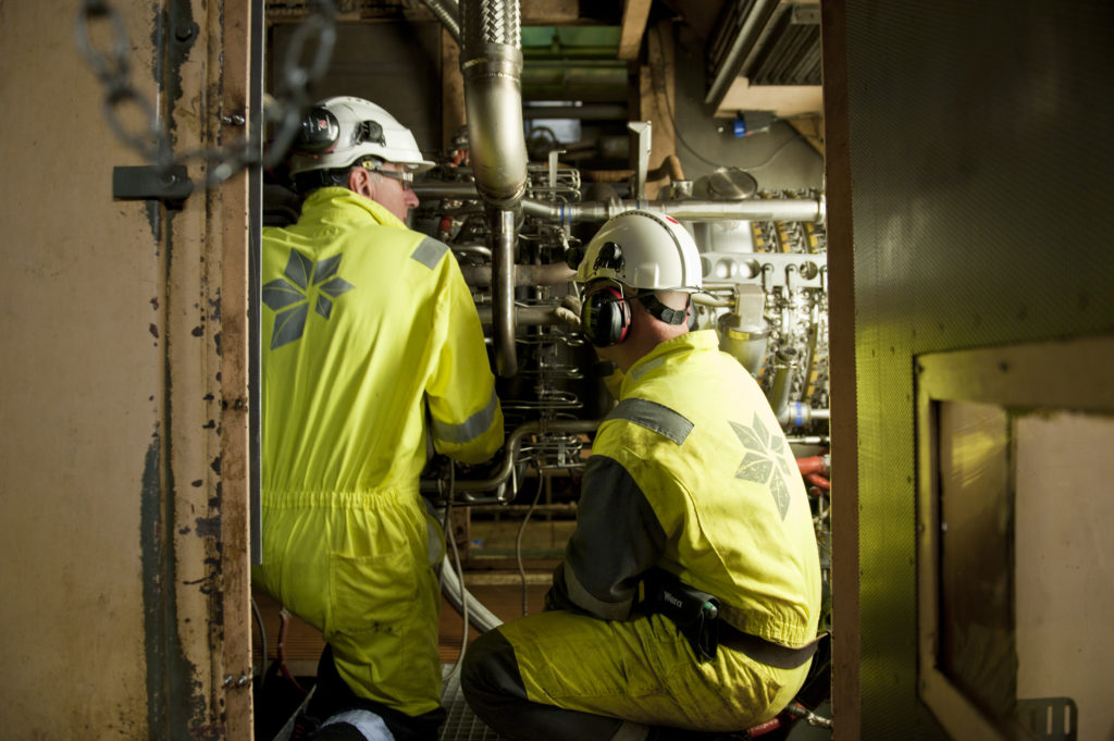
hjelpesystemer,Two workers servicing the main generator at Statfjord B. Photo: Shadé Barka Martins/Norwegian Petroleum Museum
Main electricity is supplied by three 19-megawatt generators as 13.8 kilovolt, three-phase 60 Hertz current. The generators are driven by gas/diesel turbines.
Emergency power is supplied by three 1.18 MW generators which start up automatically and connect to a 6 kV panel. If both main and emergency power systems fail, supplies of alternating and direct current will be maintained by batteries..
Electricity for the living quarters comprises the normal supply of alternating current, and emergency supplies of both alternating and direct current. The normal supply is used for air conditioning, galley equipment, heating, hot water, laundry, lifts, lighting, refrigerators, waste units and ventilation. Emergency supplies are used to maintain necessary lighting and electronic equipment.
Flaring and atmospheric ventilation
hjelpesystemer, engelsk,The flare boom at Statfjord A. Photo: Shadé Barka Martins/Norwegian Petroleum Museum
Hydrocarbons are found under varying pressure and temperature on large parts of the platform. For practical and safety reasons, some of the gas can be led to a safe place for flaring.
This can involve process gases, pressure reduction as part of an emergency procedure, or removal of gases so that maintenance can be carried out.
In the event of a total pressure dump, large volumes of gas will flow out at the tip of the flare boom. This is burnt off immediately to prevent undesirable distribution.
Tanks containing volatile liquids, which vaporise easily under atmospheric pressure, must also be vented safely. They are not all in the same place, and accordingly have dedicated vent pipes led to the sides of the platform or to points at least seven metres above the upper deck.
Monitoring and control
Process control monitors and controls all systems on the platform to ensure that hydrocarbons can be produced as safely as possible. The main functions involve:
maintaining a check on data transmission between the production system and the control-room terminals
analogue operating commands
automatic switches and logical sequence control commands
alarm logging
All this information is monitored from a central control room. Printers and displays for alarms and trends are also concentrated there to provide the operators with a good and accurate picture of conditions at all times.
hjelpesystemer, engelsk,Photo: Jan A. Tjemsland/Norwegian Petroleum Museum
Safety monitoring is a system intended to handle “all” aspects of safety on the platform. Field instrumentation and sensors for fire and gas alarms monitor the whole process and every module.
The purpose of the system is to initiate emergency shutdown of production when the process monitoring system fails to handle the problems which might occur. In principle, it comprises two systems:
1. The process shutdown system monitors the process and shuts it down if control is lost, and thereby prevents the plant being operated in a hazardous manner – under pressures higher than the tanks are designed to handle, for example.
2. The emergency shutdown system, which reacts if hazardous conditions arise – such as a gas leak or a fire. This system receives signals from fire and gas detectors as well as from manual alarms.
The metering system for production and consumption meters the quantity of gas and oil exported from the platform as well as the amount of consumption and fuel gas used internally. This system attracts great attention from all levels of the organisation, since its measurements form the basis for the revenues generated and the tax to be paid on output.
Safety and security
hjelpesystemer, engelsk,Manual alarm at Statfjord B. Photo: Shadé Barka Martins/Norwegian Petroleum Museum
Systems in this category are required for notifying and executing actions to prevent or reduce major or minor damage. They also include systems for emergency evacuation or for retrieving people who have fallen into the sea.
Fire and gasdetection All areas of the platform are fitted with fire and gas detectors. Should fires or leaks be registered, the following actions are initiated automatically:
fire pumps start
sprinkler/deluge systems are initiated (halon has been phased out)
fire dampers in the ventilation system are closed
emergency shutdown (ESD) of the platform is initiated.
Fire extinguishing system This protects personnel, structures and equipment throughout the platform (including the shafts). Two types of system are installed:
wet, using water or foam
dry, using powder (and halon earlier).
The wet system is supplied by the fire water pumps installed on the service deck. Fixed foam extinguishers are positioned in areas with a high risk of oil fires. Halon
was originally used in technical spaces which contain much electrical and electronic equipment, but has been phased out. A large powder system has been
installed in connection with the helideck. In addition, fire extinguishers – both carbon dioxide and powder – have been positioned for quick response throughout the platform
Alarms These are intended to warn of incidents which require a coordinated commitment by all personnel to saving life and maintaining platform safety. Alarms are given over the public address system, either as a signal or as a verbal announcement.
hjelpesystemer, engelsk,The survival suits hanging outside the cabins. Photo: Shadé Barka Martins/Norwegian Petroleum Museum
Rescue/safety equipment This is intended to permit speedy evacuation of personnel from the platform in an emergency, or to retrieve people who have fallen overboard. It includes:
covered free-fall lifeboats
covered rafts which inflate on contact with the sea
man-overboard boats (MOBs)
chutes for evacuation to the sea
personal survival suits.
Communication
hjelpesystemer, engelsk,Modern equipment in the radio room at Statfjord C. Photo: Jan A. Tjemsland/Norwegian Petroleum Museum
Rapid advances have been made in this area since Statfjord came on stream. The following
thereby describes both the original position and the current systems.
External communication These systems provide the necessary links between the platforms and contacts on land, at sea and in the air.
1980
The satellite system installed on Statfjord A was intended to the main carrying channel for communication between the field and the Norwegian mainland. Communication
to/from the B and C platforms was relayed over line-of-sight microwave links to Statfjord A for onward transmission. Were the satellite system to go down, VHF and MF radio communication would take over. An emergency phone system provided direct communication with land.
hjelpesystemer, engelsk,The old radio room at Statfjord A. Photo: Odd Noreger/Norwegian Petroleum Museum
The radio shack on the A platform kept in touch with helicopters via VHF (AM) radio and with ships via VHF and MF communication. Crane drivers could communicate directly with ships using VHF radio-telephones operating on the marine frequency.
A telemetry system linking the platforms was designed for fail-safe operation during transfer of crude oil between the installations. The control room on each platform monitored and coordinated the oil pumps. This system also had a speech channel for communication between the control room and the loading buoy/shuttle tanker.
Walkie-talkies were used where phones were impractical. This system provided a back-up for the phone network, the public address system and ship-to-ship communication.
The internal phone system was operated from the radio shack. This was also the location for the telex system, which was operated via the satellite link.
2010 Microwave links (point-to-point by line of sight) installed on Statfjord A and B provide the two main carrying channels from Statfjord to Gullfaks and on via fibreoptic cable to the Norwegian mainland. Should one channel drop out, all communication is automatically transferred to the other. Communicationfrom Statfjord C is transmitted via microwave links to Statfjord A and B for onward transmission to land. An emergency system provides direct mobile phone communication with land via Gullfaks.
Communication managers on the platforms maintain contact with helicopters via VHF (AM) radio and with ships using VHF. Crane drivers also communicate directly with ships using VHF radio-telephones operating on the marine frequency.
A telemetry system linking the platforms is designed for fail-safe operation during transfer of crude oil between the installations. Changes to the loading buoys (see the separate article) mean that this system is now also used for communication between platform and tanker. The control room on each platform monitors and coordinates the oil pumps. A speech channel for communication between the control room and the shuttle tanker is also provided by the telemetry system.
Walkie-talkies and the internal telephone system function by and large in the same way as they did in the 1980s. The telex system is no longer in use.
Computer network A revolution has taken place in computer technology since Statfjord came on stream. The platforms are currently equipped with a broadband network linked to Statoil’s computers on board and on land, and to the internet. This network is also used for videoconferencing between the platforms and the Statoil offices on land.
Internal communication Internal communication systems have been installed to safeguard day-to-day operation and to protect important information flows in the event of a rescue or emergency. Today’s systems have naturally been modernised, but still include a public addresssystem, intercoms, an internal telephone network, and sick bay alarms and call-outs. The original closed-circuit TV facility has been replaced today by an internal monitoring system based on video cameras, and the sickbay alarm is now provided by a pager. A significant contribution to secure communication is provided by the installation of a repeater system, which ensures radio communication coverage of the whole platform.
UHF radio communication is extensively used at present in day-to-day operation of the platform and, in the event of an alarm sounding, for search and rescue teams and the fire brigade.
hjelpesystemer, engelsk,Main control room at Statfjord B. Photo: Shadé Barka Martins/Norwegian Petroleum Museum
Control room The control room is placed in a secured area, where process operators monitor and control the various process and service systems. Two
separate monitoring and control systems are provided:
a control and information system for safe operation and shutdown, with a duplicated control system for ballast tank level
a supervisory control and data acquisition (Scada) system which monitors and checks production, drilling, transport and other connected processes.
Process data are read off automatically by the system to provide the basis for dynamic process diagrams and tabulated reports presented to the operators. Possible changes to the status of a monitored process are presented as colour changes on the displays.
person
By Harald Tønnesen and Finn Harald Sandberg, Norwegian Petroleum Museum
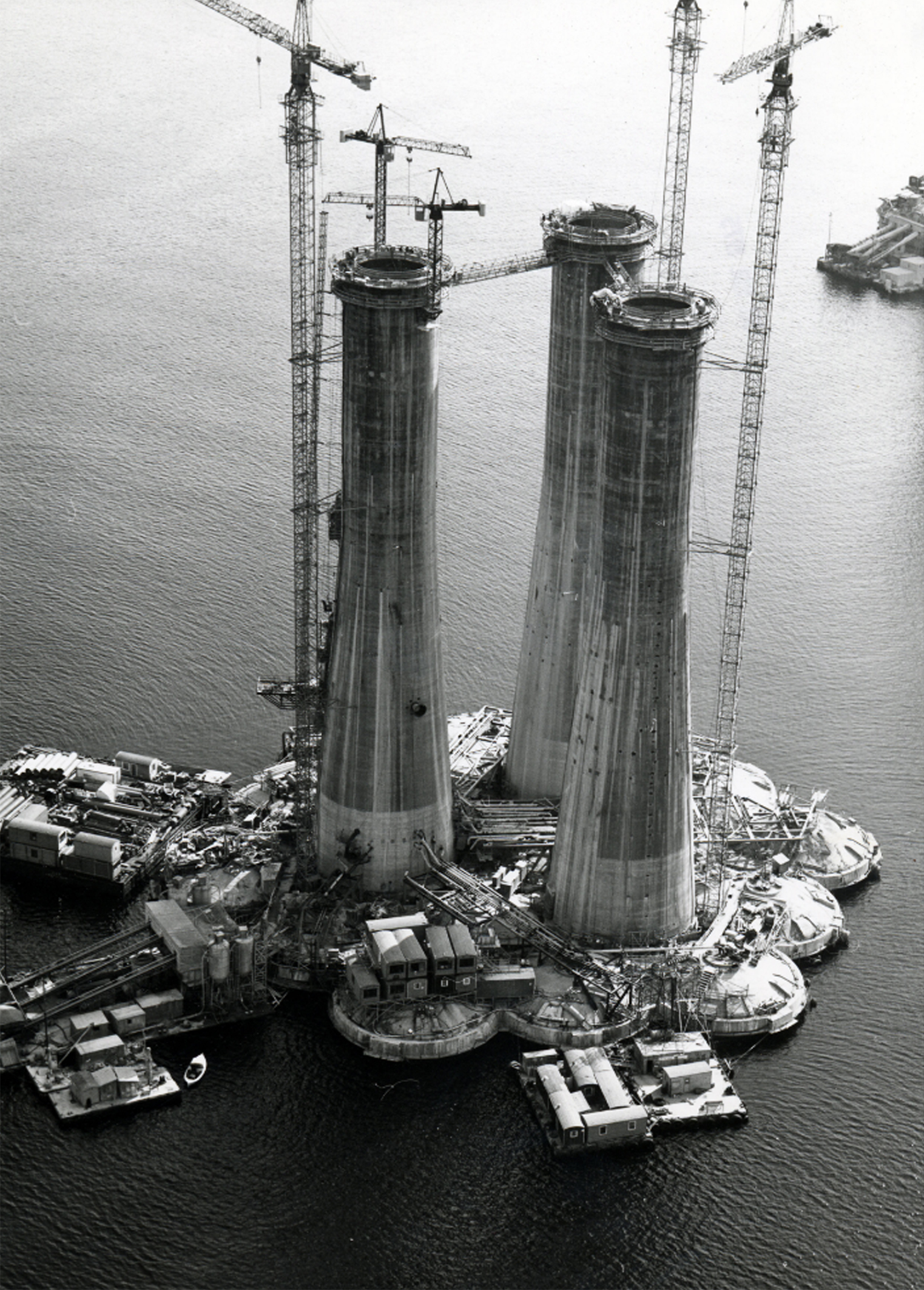
The Statfjord A platform stands in 145.3 metres of water in the centre of the field. It ranks as the fourth Condeep to be built. This installation comprises a concrete gravity base structure (GBS) supporting a steel topside . The topside was fabricated by Aker Stord in western Norway and was mated with the GBS in the adjacent Digernessund sound before tow-out to the field.
— Statfjord A platform with the two flotels Nortrym and Polymarines. Photo: Statoil on behalf of the Statfjord Group.
støping av a-en,De tre skaftene er ferdig støpt. Sementblandeverket kan ses i venstre hjørne. Foto: Norwegian Contractors//Norsk Oljemuseum
Built by Norwegian Contractors at Hinnavågen in Stavanger, the GBS comprises 19 cells arranged in a concentric formation. Most of these are used for oil storage. Three have been extended upwards as shafts to carry the topside. The platform, which measures 254 metres in height from the seabed to the top of the drilling derrick, was towed to the field in 1977 and came on stream in November 1979.
Oil was exported via a loading buoy located a few hundred metres away. The original articulated loading platform (ALP) was later replaced by a specially developed Ugland-Kongsberg offshore loading system (Ukols).
Drilling rig
The rig comprises a derrick, modules for such functions as mud mixing, and pipe storage. Wells are drilled through two of the concrete shafts supporting the topside. A total of 42 slots are provided. Both production and gas/water injection wells have been drilled, with an average depth of 2 500-2 800 metres. The derrick stands on skids which allow it to be positioned over the various wells with the aid of hydraulic jacks.
Oppkobling og ferdigstilling,
Statfjord A,
Statfjord A,
Topside
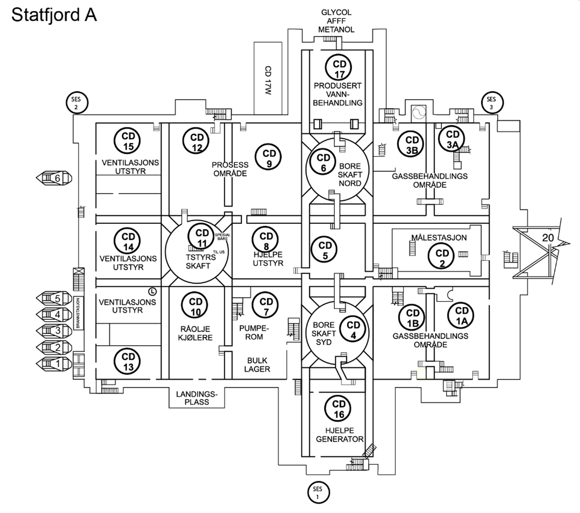
The topside measures 86.2 metres long by 83.6 wide, providing a surface area of 5 000 square metres and total deck space of 21 000 square metres. Total height to the helideck is 43.2 metres, while the base is 28 metres above the sea at its lowest point.
Cellar deck
Statfjord A,Kjellerdekk
The lowest of the steel decks, the cellar deck is built into the module support frame (MSF) which carries the rest of the superstructure. Divided into individual sections with double bulkheads, it forms an integrated steel structure. The flare boom extends for 116 metres at an angle of 45 degrees from its eastern end to burn off all associated gas for brief periods.
Module deck
Statfjord A,Moduldekk
Located above the cellar deck, this has acquired its name because it is partly composed of prefabricated modules. The south-western corner, with the M11, M12, M14,M15, M17 and M18 units, forms part of the cellar deck’s integrated steel structure.
Upper module deck
With the exception of UM7, this deck is built up entirely of modules and lies immediately above the module deck. UM7, which is part of the drilling module, has been constructed as an integrated steel structure together with the cellar deck and the south-western part of the module deck.
Statfjord A,Upper module deck
Living quarters
Bygging av A-dekket,The living quarter of Statfjord A is ready to be connected with the topside. Photo: Johan Brun/Norwegian Petroleum Museum
The living quarters provide 100 cabins. These were originally two-berth but converted for single occupancy in 2000-2003. The six-storey structure comprises three modules. A partial seventh floor is provided by the helideck, radio shack and helicopter fuel tanks. The marine control centre was positioned there in the early years, but later moved to Bergen. In addition to the cabins come a canteen and recreation rooms. A lift and internal staircase connect the floors, while external staircases serve as emergency exits. The illustration shows the layout of a typical cabin in the living quarters.
Weather deck
The tops of the uppermost modules form the weather deck. This area is used for storage and for loading/discharging cargo by the large platform cranes.
Concrete GBS
støping av a-en,Betongunderstellet til Statfjord A under bygging. Foto: Ukjent/Norsk Oljemuseum
The lower section of the GBS comprises 19 concrete cells. Sixteen of these are used for storage, while three extend upwards to form the shafts supporting the topside.
Storage cells
With an internal diameter of 19 metres and a height of 67 metres, the storage cells are individual concrete cylinders which each have a capacity of 80 000 barrels.
Fifteen of the cells are used to store crude oil, and can collectively hold about 1.2 million barrels. Cell 6 is equipped with an internal cylindrical tank to store up to 21 750 barrels of diesel oil. The annulus between the internal cylinder and the cell wall provides 63 500 barrels of storage space for the oil-water emulsion (sludge) which forms during platform operation. All 16 of the cells are partly filled with sand ballast covered by a concrete lid. They are kept filled with liquid at all times. When oil is exported, the cells take in water to maintain their liquid content.
Utility shaft
Statfjord A,Inside one of the utility shafts. Photo: Aker/Norwegian Petroleum Museum
One of the three shafts supporting the topside, this contains a series of decks carrying pumps for fire, ballast and sea water, ballast water tanks and pumps for crude oil loading.
Drilling shafts
These are completely filled with conductor tubing for a total of 16 wells in each shaft. The illustration shows the distribution between production and water/gas injection wells.
Statfjord A,Statfjord A. Photo: Marit Hommedal/Equinor
person
by Trude Meland, Norwegian Petroleum Museum
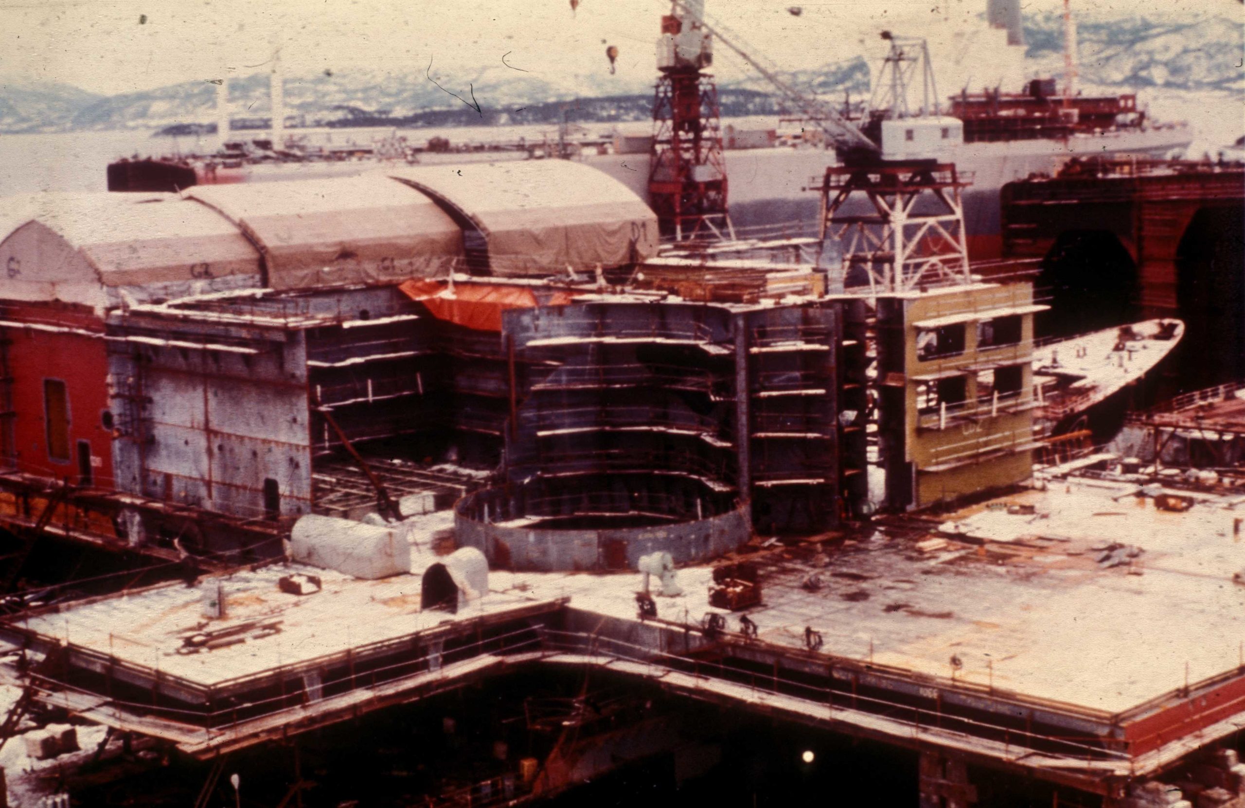
The Aker group had been commissioned by Mobil in August 1974 to fabricate and outfit the topside for Statfjord A. It had already undertaken similar contracts – Vindholmen Verft in Arendal had built the topside for Beryl A and Aker Verdal north of Trondheim was building a similar structure for Shell/Esso’s Brent B. Both these platforms were destined for the UK sector of the North Sea.
— The Statfjord A topside under construction in the dry dock of Aker Stord. Two old hulls, named Tom and Tina, were used as "foundations" for this work. Photo: Tor Resser/Norwegian Petroleum Museum
Under the letter of intent signed between Mobil and Aker, the module support frame (MSF) for Statfjord A would be fabricated at Aker Verdal with outfitting by Aker Offshore Contractors (AOC). The latter also had the contract for mechanical outfitting in the shafts of the concrete gravity base structure (GBS).
When it turned out that the topside would be larger and heavier than first agreed, the Aker Verdal yard ran into capacity problems.[REMOVE]Fotnote: Haga, T. (1993). “Stordabuen går offshore” : Arbeid og faglig politikk ved A/S Stord verft 1970-83 (Vol. 1993-4, AHS (trykt utg.)). Bergen: Gruppe for flerfaglig arbeidslivsforskning, Universitetet i Bergen: 260. Stord Verft south of Bergen, which had only built ships – primarily oil tankers – before, was hit when the tanker market collapsed in the wake of the oil crisis. An order for 11 supertankers was cancelled, leaving the yard short of work.[REMOVE]Fotnote: Grove, K., Heiret, J., & Stord jern- & metallarbeiderforening. (1996). I stål og olje : Historia om jern- og metallarbeidarane på Stord. Stord: Stord metall- og bygningsarbeider[e]s fagforening: 161. og Myklebust, A., & Aker Stord A/S. (1994). 75 år på Kjøtteinen : 1919-1994 : Jubileumsbok for Aker Stord. Stord: [Aker Stord].
Bygging av A-dekket,Statfjord A topside under construction at Stord Verft. Photo: Aker Mekaniske Verksted/Norwegian Petroleum Museum
Aker accordingly submitted a proposal to Mobil in February 1975 to transfer the job of building the Statfjord A topside from Verdal to Stord. Mobil accepted this, and Stord Verft thereby acquired its first offshore assignment. The contract was signed on 5 April 1975.[REMOVE]Fotnote: Moe, J. (1980). Kostnadsanalysen norsk kontinentalsokkel : Rapport fra styringsgruppen oppnevnt ved kongelig resolusjon av 16. mars 1979 : Rapporten avgitt til Olje- og energidepartementet 29. april 1980 : 2 : Utbyggingsprosjektene på norsk sokkel (Vol. 2). Oslo: [Olje- og energidepartementet]: 178.
But Stord Verft was soon to discover that fabricating offshore structures differed significantly from shipbuilding. While the latter was a form of mass production, a platform had to be custom-built.
Bigger than expected
The original contract allowed Stord Verft to take on a wider scope of work. As initially conceived, the topside was to comprise a single MSF where the equipment was installed in modular form – almost like a large Lego construction.
Bygging av A-dekket,The Statfjord A topside is starting to take shape. Foto: Aker Mekaniske Verksted/Norwegian Petroleum Museum
Since the yard had spare capacity, however, Aker initiated negotiations with Mobil on a new integrated structure. Rather than all the modules forming a conventional modular system, the support structures for a number of these would be incorporated in the MSF, and their equipment then installed in them.
The contract with Aker’s Stord Verft embraced the following elements.
Design and fabrication of the steel topside, with an estimated weight of 6 800 tonnes. This included steel procurement, towing the topside to the mating site and mating with the Condeep GBS.
Design and fabrication of the MSF for the integrated M6, M8, M11, M12, M14, M17, M18 and UM7 modules and installation of the deck, with an estimated weight of 1 828 tonnes. This also included steel procurement.
Outfitting the cellar deck and the above-mentioned modules. This would be done to the extent that approved drawings, specifications, equipment and materials were available at Stord Verft.
While contract negotiations were under way between Aker and Mobil, appraisal wells being drilled on Statfjord revealed that the field was larger than originally thought. On the basis of that knowledge, it was resolved to double production capacity on the platform from 150 000 barrels per day to 300 000. In order to be able to handle such large volumes of oil, the topside facilities had to be expanded from one to two process trains. That naturally doubled the size and weight of the equipment. This in turn meant that the MSF had to be strengthened to handle the weight.[REMOVE]Fotnote: Moe, J. (1980). Kostnadsanalysen norsk kontinentalsokkel : Rapport fra styringsgruppen oppnevnt ved kongelig resolusjon av 16. mars 1979 : Rapporten avgitt til Olje- og energidepartementet 29. april 1980 : 2 : Utbyggingsprosjektene på norsk sokkel (Vol. 2). Oslo: [Olje- og energidepartementet]: 141.
A partially integrated topside would be significantly more complicated, but Aker justified the design changes submitted to Mobil on 6 February 1975 by noting that steel weight would be reduced. Mobil accepted the revised design and a new contract was signed on 5 April 1975.[REMOVE]Fotnote: Moe, J. (1980). Kostnadsanalysen norsk kontinentalsokkel : Rapport fra styringsgruppen oppnevnt ved kongelig resolusjon av 16. mars 1979 : Rapporten avgitt til Olje- og energidepartementet 29. april 1980 : 2 : Utbyggingsprosjektene på norsk sokkel (Vol. 2). Oslo: [Olje- og energidepartementet]: 178.
This meant a welcome increase in the scope of work for Stord Verft. A number of the modules were originally due to be fabricated at other yards and engineering works in Norway and abroad which were also struggling with the after-effects of the oil crisis. Because Stord Verft was now going to integrate these modules in the MSF, the other fabricators lost sorely needed work.[REMOVE]Fotnote: Moe, J. (1980). Kostnadsanalysen norsk kontinentalsokkel : Rapport fra styringsgruppen oppnevnt ved kongelig resolusjon av 16. mars 1979 : Rapporten avgitt til Olje- og energidepartementet 29. april 1980 : 2 : Utbyggingsprosjektene på norsk sokkel (Vol. 2). Oslo: [Olje- og energidepartementet]: 183. Modules were built by Kværner/Sterkoder in Egersund and Kristiansund (M1A, M1B, M2, M10, M13, M16, UM8, UM9 and the toolroom), Nordland Offshore A/S in Sandnessjøen (UM9B and the telecommunications module), Bodø Mekaniske Verksted (UM2 and M10 top), Wilson Walton, Middlesbrough (M3, M5 and M9), and Curtis Wright/RSV in Rotterdam (M4A, M4B, UM5 and UM6). In addition, Norway’s Leirvik Sveis completed M9.
In retrospect, it is clear that the local management at Stord Verft took an unrealistic view of the transition from shipbuilding to platform construction. A topside for what then ranked as the world’s largest offshore installation was far more complicated, and new standards had to be met – particularly for welding.
The amount of engineering design work was greatly underestimated, and detailed design proved the first casualty. While the yard had been accustomed to using its own drawing office, it now received detailed drawings from Matthew Hall Engineering (MHE) in London. The latter had the contract for the technical design of outfitting and process equipment.
Design job too extensive
MHE had won an engineering management contract (EMC) for the Statfjord A topside (see the section on the construction contracts for more details). This job embraced conceptual and technical design, management of process equipment and modules – including procurement – award of fabrication contracts and construction site supervision.
Although the EMC had been put out to competitive tender, a tight market meant that Mobil received only two bids. The operator had been concerned from the start about MHE’s lack of experience with similar projects, but had no choice but to award it the contract if the schedule was to be maintained.[REMOVE]Fotnote: Moe, J. (1980). Kostnadsanalysen norsk kontinentalsokkel : Rapport fra styringsgruppen oppnevnt ved kongelig resolusjon av 16. mars 1979 : Rapporten avgitt til Olje- og energidepartementet 29. april 1980 : 2 : Utbyggingsprosjektene på norsk sokkel (Vol. 2). Oslo: [Olje- og energidepartementet]: 168.
It quickly transpired that the design work failed to meet the required standard and would be delayed. MHE had estimated 400 000 hours for the work, with 90 per cent completed by the end of 1975. But the company ran into problems.
In addition to insufficient experience with such projects, it lacked enough personnel and had up to 80 per cent contract workers at one point. When the decision was taken to change the concept to a partly integrated topside, MHE had already been working for nine months on planning the process equipment. A completely new concept meant that the company had to start all over again, and many working hours were wasted.[REMOVE]Fotnote: Moe, J. (1980). Kostnadsanalysen norsk kontinentalsokkel : Rapport fra styringsgruppen oppnevnt ved kongelig resolusjon av 16. mars 1979 : Rapporten avgitt til Olje- og energidepartementet 29. april 1980 : 2 : Utbyggingsprosjektene på norsk sokkel (Vol. 2). Oslo: [Olje- og energidepartementet]: 169.
Only 50-60 per cent of the design work was completed in January 1976, and the number of hours was four times higher than the estimate. Mobil resolved to cancel the contract with MHE and brought in a US engineering contractor – Brown & Root – to replace the London-based company on a gradual basis. Mobil regarded Brown & Root as the best qualified candidate for the job, and awarded the contract without competitive tendering.
In October 1975, Brown & Root also took over the contract for planning, management and execution of offshore hook-up work from MHE. It already had the job of technical design and management for work on the loading buoy, flare boom and flowlines.[REMOVE]Fotnote: Moe, J. (1980). Kostnadsanalysen norsk kontinentalsokkel : Rapport fra styringsgruppen oppnevnt ved kongelig resolusjon av 16. mars 1979 : Rapporten avgitt til Olje- og energidepartementet 29. april 1980 : 2 : Utbyggingsprosjektene på norsk sokkel (Vol. 2). Oslo: [Olje- og energidepartementet]: 156. This meant that the company now held all three of the major assignments for completing Statfjord A.
Topside weight increases
The factor which caused the biggest problems in planning and building Statfjord A was a massive underestimating of the weights involved.
Bygging av A-dekket,Stord Shipyard estimated the hours of extra work as result of the weight problems to 150,000 hours, which corresponded to about NOK 75 million including materials. Another consequence of the reinforcement work was failure in the supply of materials. The amount of steel ordered was based on the initial estimates and was therefore too small. With a tight market, delivery time was long. Photo: Aker/Norwegian Petroleum Museum
A platform’s weight can be measured in two ways – wet and dry. Wet weight is measured in operating condition with the various process components are filled with liquids. The GBS and topside are designed to cope with a given weight, and the wet weight must not exceed that level. The dry weight is the sum of MSF and equipment alone. A platform is towed out fully or partly outfitted, and the dry weight of the topside must not exceed the tow-out value.[REMOVE]Fotnote: Rolstadås, A., & Norges tekniske høgskole Institutt for verkstedteknikk. (1981). Prosjektstyring. Trondheim: Tapir: 137.
MHE lacked a satisfactory system for either wet or dry weight control. The most accurate possible weight estimates for both MSF and production equipment were already required in early 1975 in order to design the topside. But the wet weight calculations produced by MHE were too low.
Disputes arose between the design company on the one hand and Stord Verft/Aker on the other about the loadbearing capacity of the topside. MHE’s estimate was 34 500 tonnes, while the contract with Stord Verft stipulated 41 500 tonnes. The overall weight ultimately came to 49 500 tonnes. Extensive design work was required to ensure that the MSF could bear this weight. That in turn led to big delays and significantly more expensive fabrication work.[REMOVE]Fotnote: Moe, J. (1980). Kostnadsanalysen norsk kontinentalsokkel : Rapport fra styringsgruppen oppnevnt ved kongelig resolusjon av 16. mars 1979 : Rapporten avgitt til Olje- og energidepartementet 29. april 1980 : 2 : Utbyggingsprosjektene på norsk sokkel (Vol. 2). Oslo: [Olje- og energidepartementet]: 164.
During the fabrication period, MHE’s engineers fell behind with the design work. In an attempt to speed up progress with the technical design, MHE issued incomplete drawings. This meant that the number of drawing revisions and fabrication changes increased. When drawings were amended, structures already installed had to be ripped out and the work done again.
Tow-out weight restriction
The tow-out or dry weight also caused problems. The loadbearing capacity of the Condeep imposed restrictions on the amount of equipment which could be positioned topside before departure for the field.
It turned out that the maximum tow-out weight was significantly lower than the hardware to be installed. Modules accordingly had to be removed for installation once the platform had been positioned on Statfjord. Such assembly and disassembly, both for this reason and because of revised drawings, had a negative effect on the motivation of the workforce at the Stord yard.
Welding is not just making welds
Welders were the largest group of workers involved in fabricating the Statfjord topside. They quickly discovered that welding tankers and oil installations were two different exercises. The former demanded other material types and thicknesses than were used on ships, and the new kind of steel demanded a different welding technique. In addition, the quality of the work had to be improved and its accuracy improved.
Mobil required that all the welders were certified to specified standards. Instead of the earlier approval by Norway’s Det Norske Veritas (DNV), the American ASME norm was introduced. This was divided into six levels, from 1G as the lowest up to 6G. To secure a 6G certificate, a welder had to be able to weld around a pipe positioned at an angle of 45 degrees while welding “through” – in other words, so that the joint is filled.
Many former ship welders failed to pass the tests for the new certificates, and the yard eventually had problems securing sufficient skilled personnel. Since the work was already behind schedule, the management wanted to bring in foreign welders. But this had first to be cleared with the unions. Welders were brought in from other Aker companies to help out. The shortage of welders meant that prefabrication lagged behind, and delays there had a knock-on effect on assembling the topside.
Welds were carefully X-rayed and checked. The yard was told that each weld had to be marked with a number, so that possible faults could be traced directly back to the welder who had done the job. As the work progressed, it became clear that a number of welds had to be redone. If the checks showed more than five per cent error in a weld, it was rejected. A welder who had too many rejects had to be recertified.[REMOVE]Fotnote: Grove, K., Heiret, J., & Stord jern- & metallarbeiderforening. (1996). I stål og olje : Historia om jern- og metallarbeidarane på Stord. Stord: Stord metall- og bygningsarbeider[e]s fagforening: 170. By March 1976, fabrication was far behind schedule.
Pipework
The pipefitters also found that their work changed with the transition from ships to platforms. There was considerably more pipework and it was more monotonous. The piping was prefabricated and much of the work previously done by the fitters arrived ready-made. Piping was lifted on board from the warehouse by crane.
When ships were still being built, detailed drawings were supplied by the yard’s own engineers, but the individual foreman or fitter could change them if he found it appropriate. That was no longer the case.[REMOVE]Fotnote: Grove, K., Heiret, J., & Stord jern- & metallarbeiderforening. (1996). I stål og olje : Historia om jern- og metallarbeidarane på Stord. Stord: Stord metall- og bygningsarbeider[e]s fagforening: 169. Drawings supplied from London had to be followed to the smallest detail, and all changes had to be reported. The independence and scope of the work was reduced.[REMOVE]Fotnote: Myklebust, A., & Aker Stord A/S. (1994). 75 år på Kjøtteinen : 1919-1994 : Jubileumsbok for Aker Stord. Stord: [Aker Stord].
Working conditions in the workshops were also poor. The worst problem was the heat. The platform steel had to be preheated to 150°C before it could be welded. Although fresh air was blowing into the welding areas to thin out the gases, no effective ventilation was in place. There were smoke and fumes everywhere, while greater use of angle grinders and carbon rod welding increased the noise level.
The Stord Verft workforce noted the transition to the offshore industry directly. Their work became less independent, delivery times were shorter and physical working conditions deteriorated. The many change jobs had an unfavourable impact of their morale, and productivity declined.[REMOVE]Fotnote: Grove, K., Heiret, J., & Stord jern- & metallarbeiderforening. (1996). I stål og olje : Historia om jern- og metallarbeidarane på Stord. Stord: Stord metall- og bygningsarbeider[e]s fagforening:172.
To offset this decline in efficiency, the workforce was expanded to 950 people between June and December 1976. But this did not increase the amount of work actually done.
Designing equipment which was to last “for ever”, and which would never again be seen or accessed, was unusual and challenging. No design codes existed for offshore petroleum projects in 1975. When mechanical engineer Einar Jensen at AOC worked on the rotating machinery, he and his team used design codes developed by Mobil for use on land and DNV codes for shipboard use.
Nobody had ever designed such a large and complex structure as Statfjord A, with all its criss-crossing pipes.[REMOVE]Fotnote: Interview with Eilef Lynghaug, Einar Jensen and Jan-Henry Larsen, former platform managers on Statfjord, by Trude Meland, Norwegian Petroleum Museum, 18 September 2008. To begin with, all the piping was marked. But these marks were subsequently covered with insulation, so the work was wasted.
Postponement
Bygging av A-dekket,The Statfjord A topside at Stord Verft. Photo: Aker Mekaniske Verksted/Norwegian Petroleum Museum
Mobil eventually grasped the seriousness of the position, and realised that tow-out of the platform would have to be postponed for a year. It could not go out to the field before the summer of 1977.
In statements to the media, the company emphasised that more of the work on the installation could thereby be done inshore rather than more expensively and lengthily out on the field:
“The more equipment which can be installed on the platform while it is inshore ¬– according to plans, at Stord, the better. In this way, the time at land can be exploited and difficult and expensive work avoided on the field in the North Sea.”[REMOVE]Fotnote: Stavanger Aftenblad, 13 May 1976. “Størst mulig last en fordel”.
Because of the maximum tow-out weight, however, this plan could not be fully implemented.
Despite the problems, the MSF was eventually completed. This work had taken place in the yard’s dry dock, but the gates were opened on 30 July 1976 and the structure was towed out into the fjord. At the same time, the GBS was on its way from Stavanger to Stord.
The MSF had been built on two redundant tankers – known as Tom and Tina. When the topside was to be mated with the GBS, the latter was ballasted down until it was almost entirely submerged and the two tankers were manoeuvred between the concrete shafts.
Deballasting the storage cells then raised the GBS, so that the topside was carefully positioned on and then lifted by the shafts.[REMOVE]Fotnote: Godø, H. (1980). Plattformutbygging til havs (Vol. Nr 11-1980, Sosialdepartementets sammendragsserie (rapportsammendrag : trykt utg.)). Oslo: Sosialdepartementet: 45. This mating operation took place on 8 August 1976, and work then continued out in Digernessundet.
Leaks
But the problems were not over. Cracks in the GBS were discovered in 1976 during maximum submersion in connection with the mating operation. They had arisen as a result of excessive temperature fluctuations and a weak section in the concrete. It took two months to repair the damage.[REMOVE]Fotnote: Hanisch, T., Nerheim, G., & Norsk petroleumsforening. (1992). Fra vantro til overmot? (Vol. 1). Oslo: Leseselskapet: 392. Einar Jensen experienced this episode:
“It was a Friday evening, I think, and we were on our way home to Stavanger. When the high-speed ferry berthed, the project manager was standing there and waving us to one side. We went directly to Sola [airport] and into a specially booked plane. Statfjord A was listing. The platform was shipping water in its cells. Four-five of us were involved. There was little drama, but we took in a good deal of water and didn’t know where it was coming from.”[REMOVE]Fotnote: Interview med Einar Jensen by Trude Meland, Norwegian Petroleum Museum, 2 October 2008.
It transpired that there were two cracks, each 20 centimetres long, in the concrete between one “star” cell and a storage cell. The GBS was taking in 15 000 litres of water per hour or 20 buckets a minute.[REMOVE]Fotnote: Stavanger Aftenblad, 14 September 1976. “20 bøtter i minuttet”. But the structure was never in any danger of tipping over or sinking. The pumps installed in the GBS were capable of discharging a million litres per hour, and had no problem controlling the water intrusion. Without the pumps, the GBS would have sunk 60-70 centimetres per day because of the extra displacement caused by the water.
People from AOC and Norwegian Contractors (NC) devoted the weekend to identifying what had happened. When the cracks were located, NC – the company responsible for the concrete structure – injected them with epoxy, a special and elastic form of concrete. Sealing the cracks was a big job, and the incident led to delays. Installing such modules as the living quarters and the helideck had to be postponed until the damage was repaired.[REMOVE]Fotnote: Hanisch, T., Nerheim, G., & Norsk petroleumsforening. (1992). Fra vantro til overmot? (Vol. 1). Oslo: Leseselskapet: 392.
Two months later, Statfjord A listed again while it was lying in Digernessundet. A test of the emergency shutdown procedure for the ballast system went wrong. The living quarters had been installed at one end of the topside, and differing levels of ballast water in the various cells was used to compensate for the added weight. A service operative from the Swedish factory which had delivered the ballast system was going through the procedure for testing the hydraulics. Einar Jensen reports what happened:
“The procedure involved placing each valve in a semi-open position, and then pressing a red button and timing how long it took to shut down. There were 16 cells with ballast water. He tested first one valve and then another. Everything seemed to be working fine. The final stage in the procedure was to place all the valves in a semi-open position and then press the big button. Since we had varying water levels, things began to happen and the platform started to list. The alarms sounded, and the big button fortunately worked. We had a well-qualified man in the control room who pressed the button as soon as he saw the platform begin to list.”[REMOVE]Fotnote: Interview med Einar Jensen by Trude Meland, Norwegian Petroleum Museum, 2 October 2008.
The procedure followed would have been correct for a system which was not in operation. Since the system on Statfjord A was in fact operational, the final stage should have been left out.
This was a serious incident. The platform listed by three degrees, which means that the topside sank by eight-nine metres along one side.[REMOVE]Fotnote: Gjerde, K., Ryggvik, H., & Gooderham, R. (2014). On the edge, under water : Offshore diving in Norway. Stavanger: Wigestrand: 158. It was evacuated, and nobody was hurt. Subsequent reports have alleged that people jumped from the topside, but Jensen denies this:
“People didn’t jump from the topside, but a scaffolding ladder was installed on each side down to a barge on the water. When the platform listed, the stair on one side became far too short, so that when you reached the bottom step the surface was still some way down. It’s possible that some people who went down those stairs jumped, but I can’t confirm it.”[REMOVE]Fotnote: Interview med Einar Jensen by Trude Meland, Norwegian Petroleum Museum, 2 October 2008.
When Mobil decided that the tow-out of Statfjord A should be postponed by a year, a new date was also set – 3 May 1977. That deadline was met, and the platform was in position on the field by 8 May.
Grouting – filling the space between the GBS base and the seabed with gravel – started two days later. The remaining work of completing Statfjord A and readying it for production could then begin. Much work and many challenges were still to come.


 hjelpesystemer, engelsk,
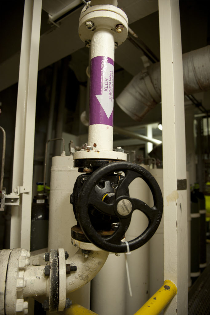 hjelpesystemer, engelsk,
 Statfjord C, hjelpesystemer, engelsk,
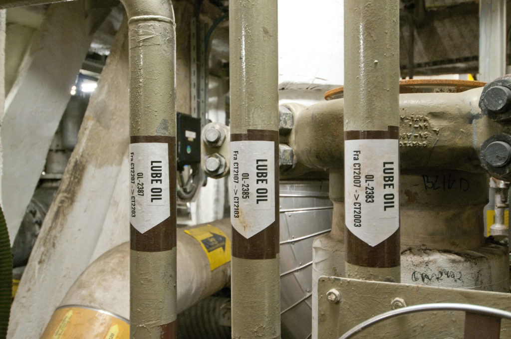 hjelpesystemer, engelsk,
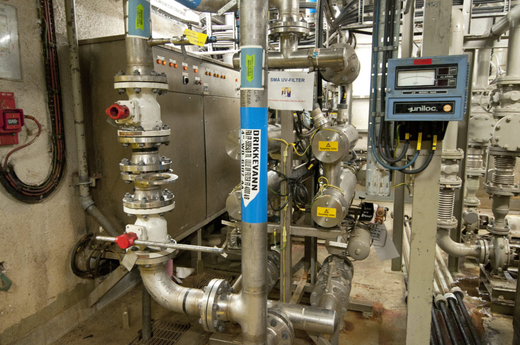 Statfjord A, hjelpesystemer, engelsk,
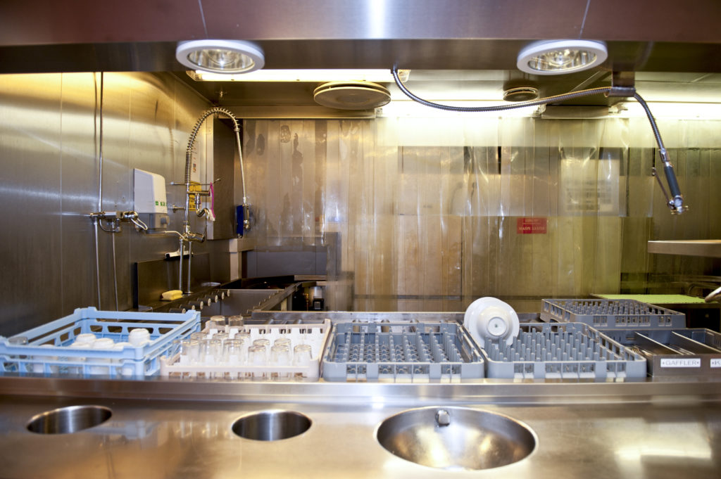 hjelpesystemer, engelsk,
 hjelpesystemer, lasting,
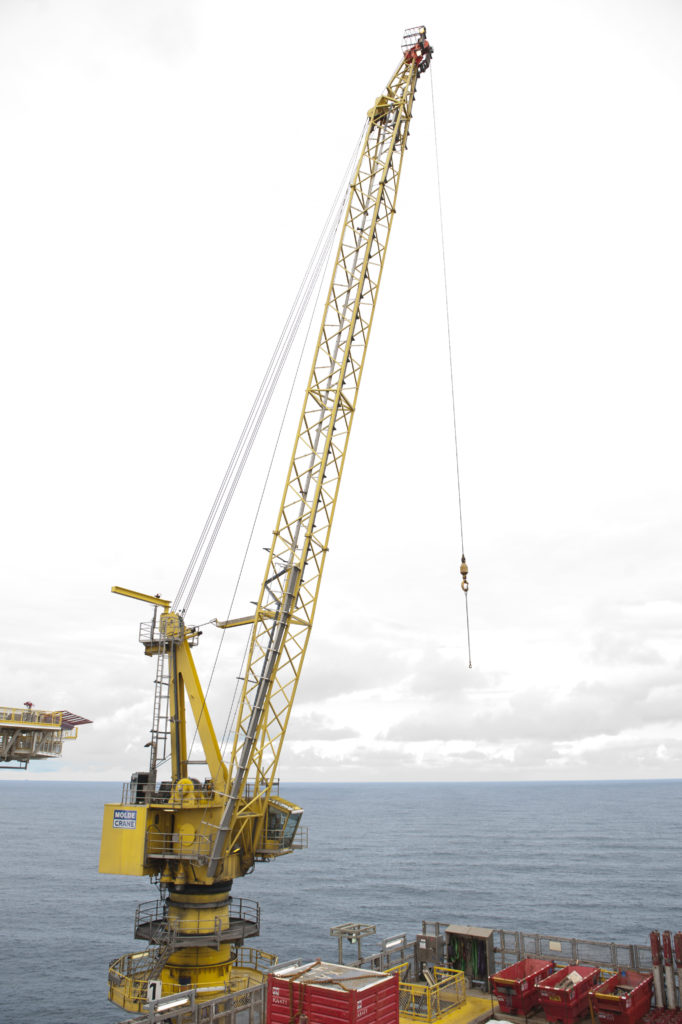
 hjelpesystemer,
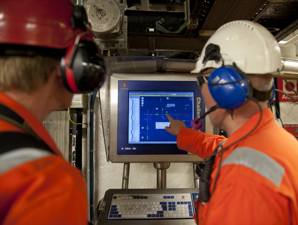 hjelpesystemer, engelsk,
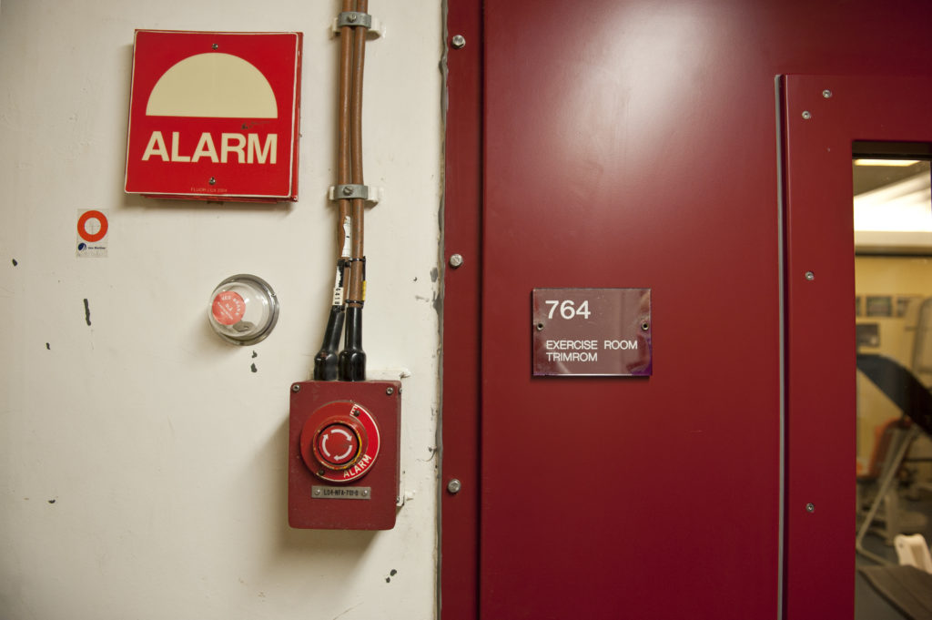 hjelpesystemer, engelsk,
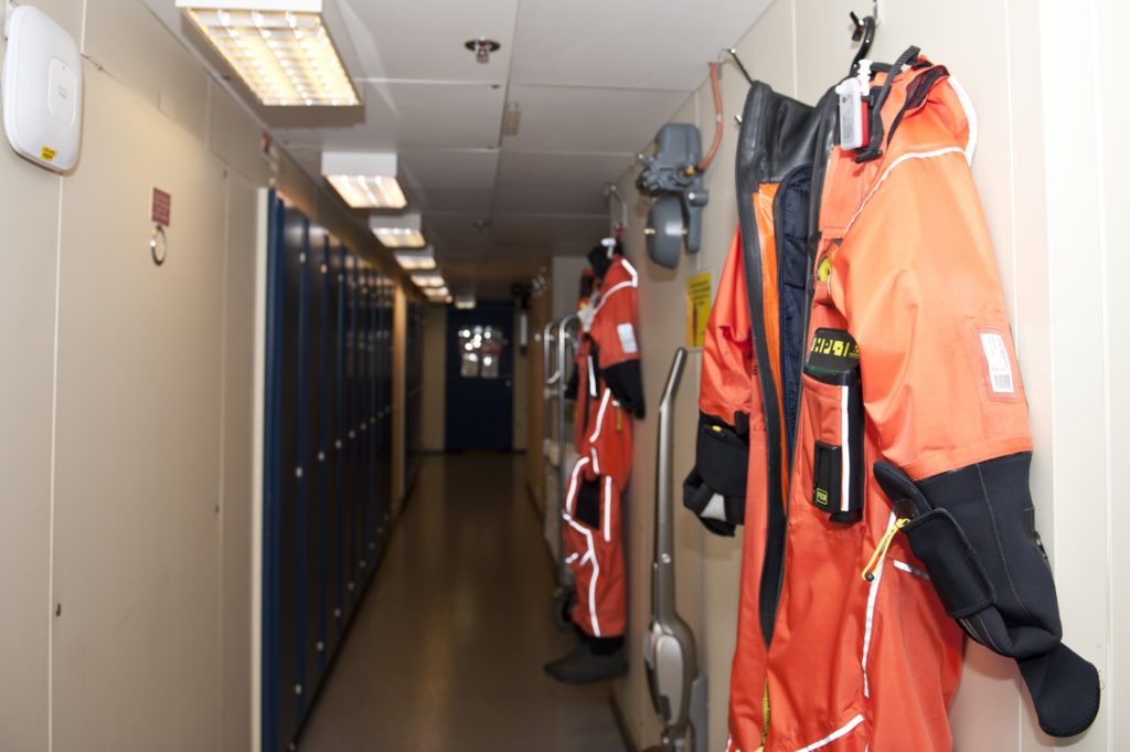 hjelpesystemer, engelsk,
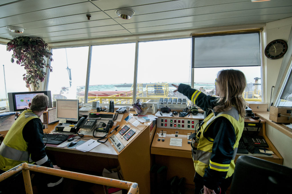 hjelpesystemer, engelsk,
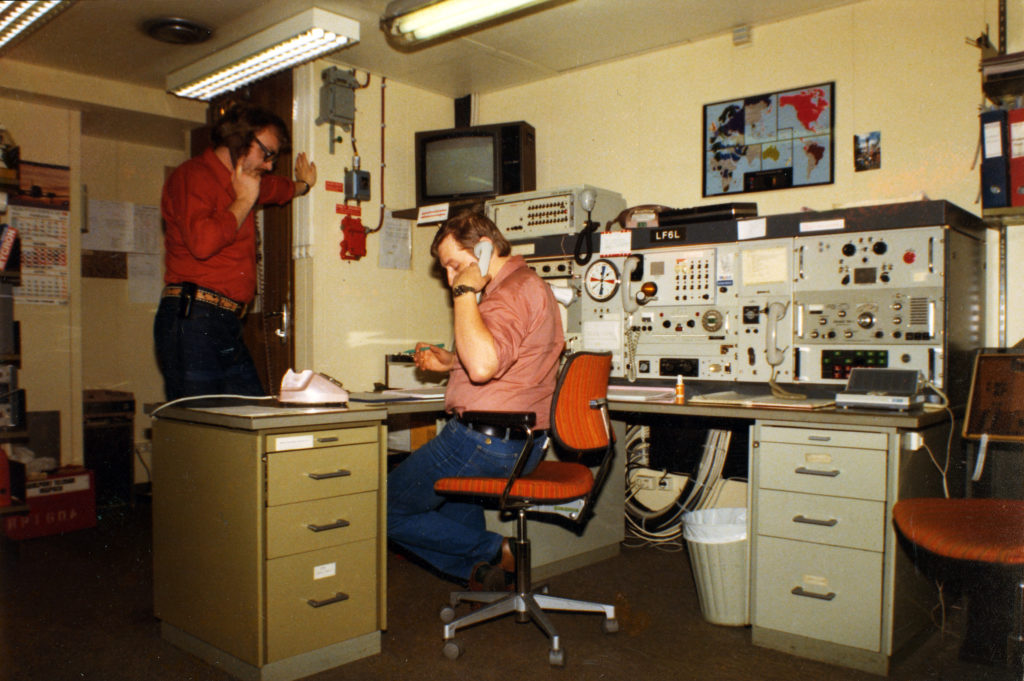 hjelpesystemer, engelsk,
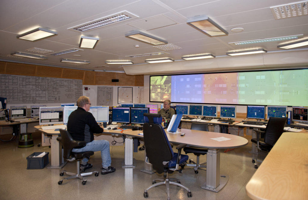 hjelpesystemer, engelsk,
 støping av a-en,


 Statfjord A,
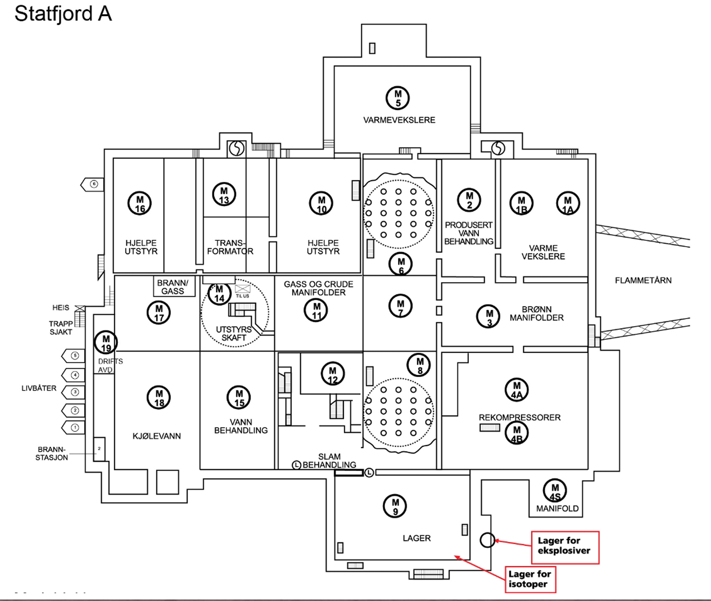 Statfjord A,
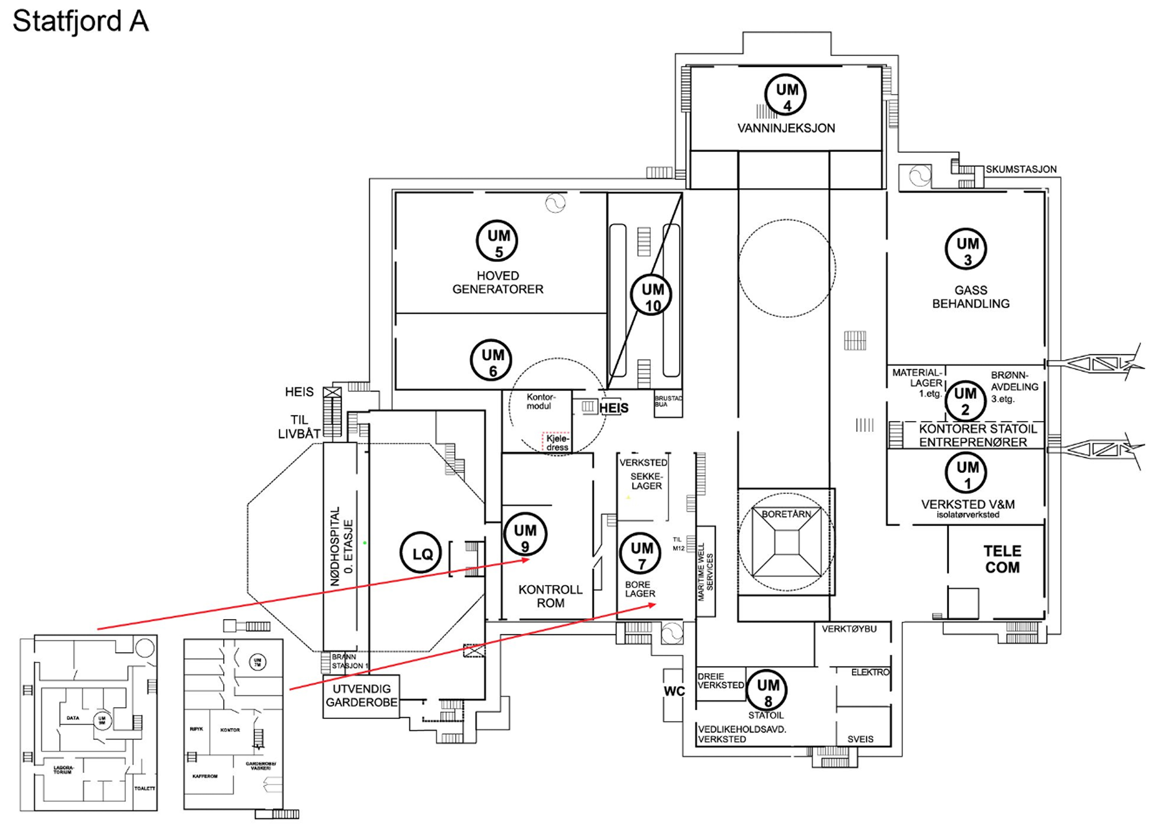 Statfjord A,
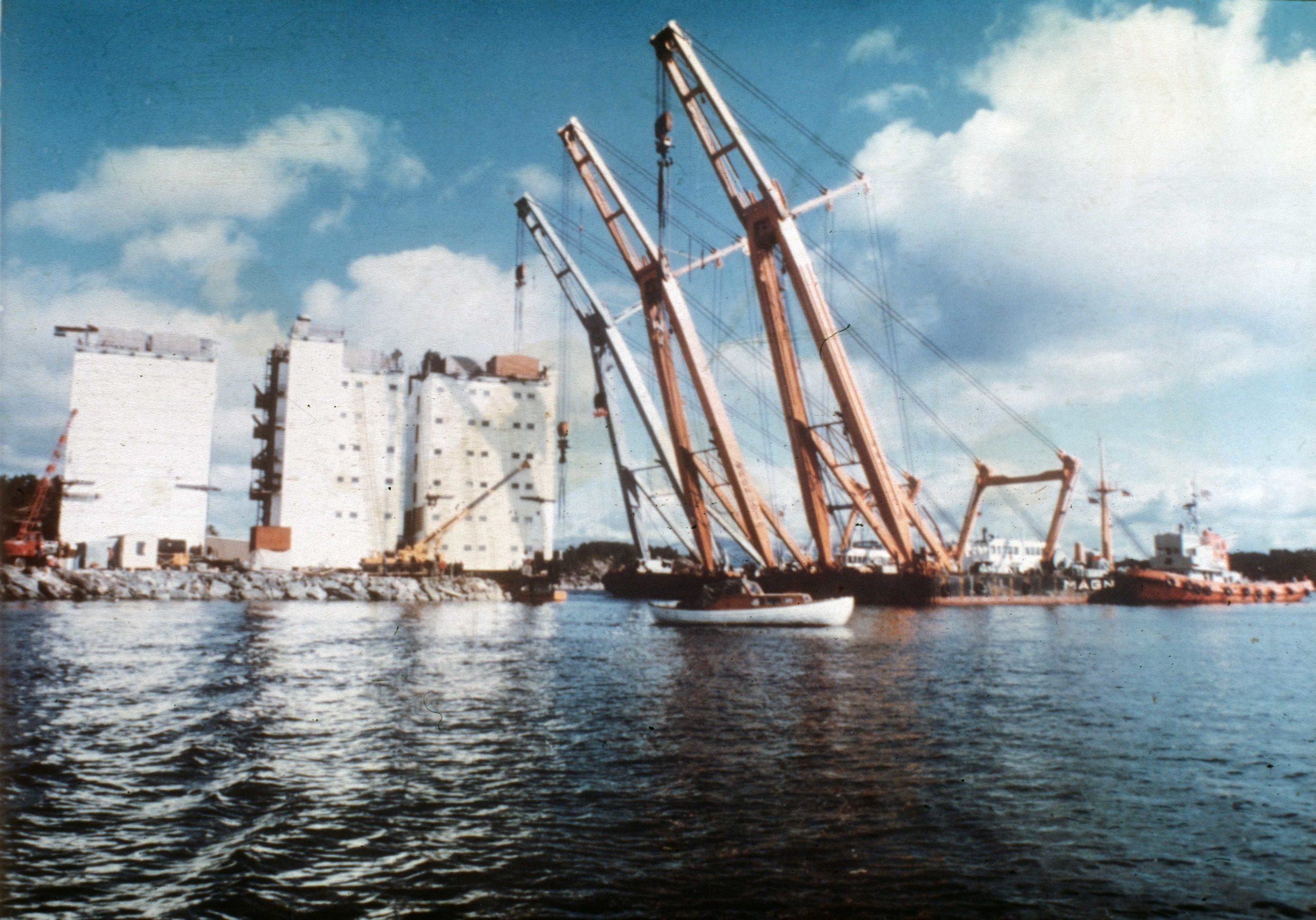 Bygging av A-dekket,
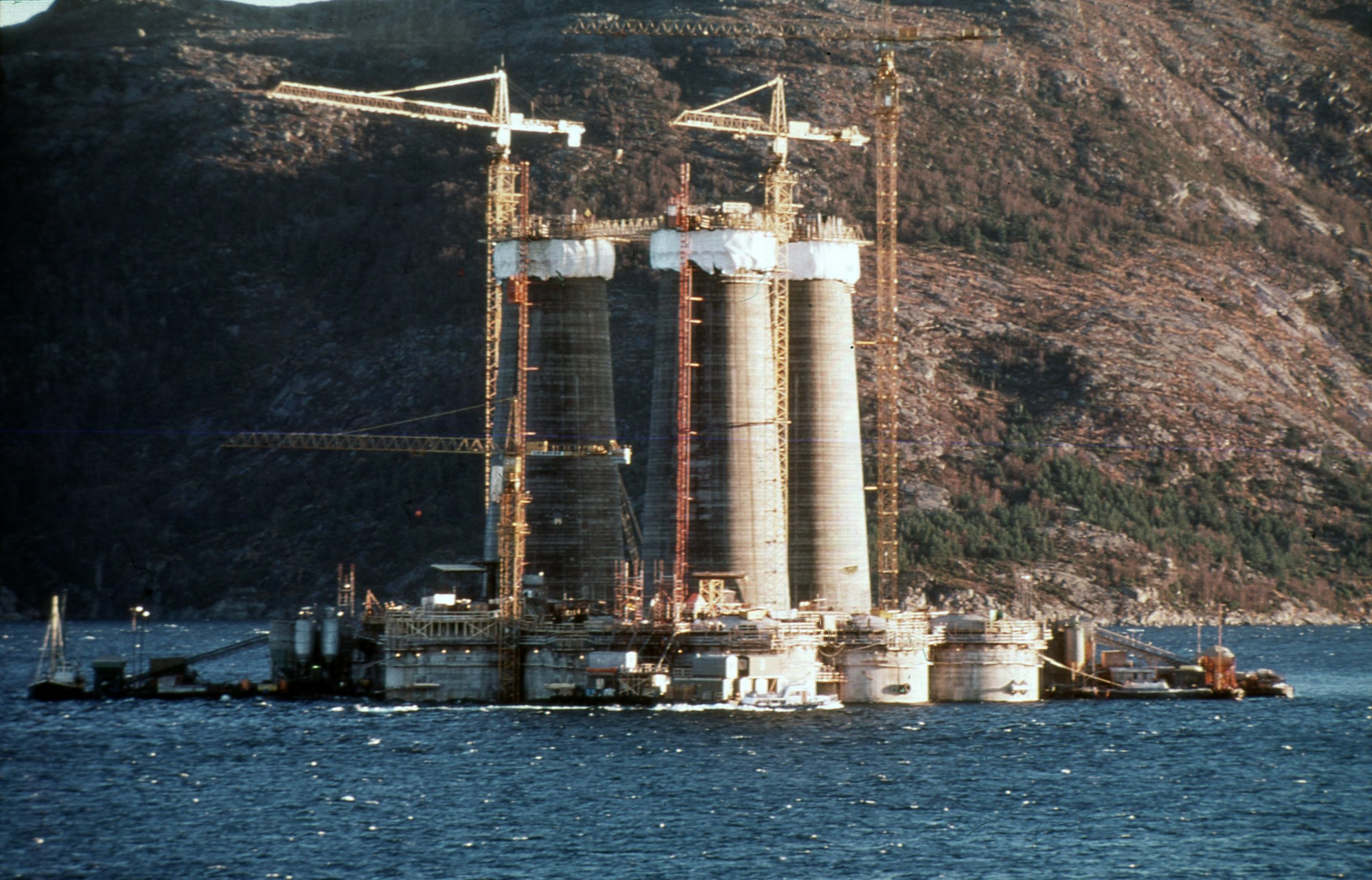 støping av a-en,
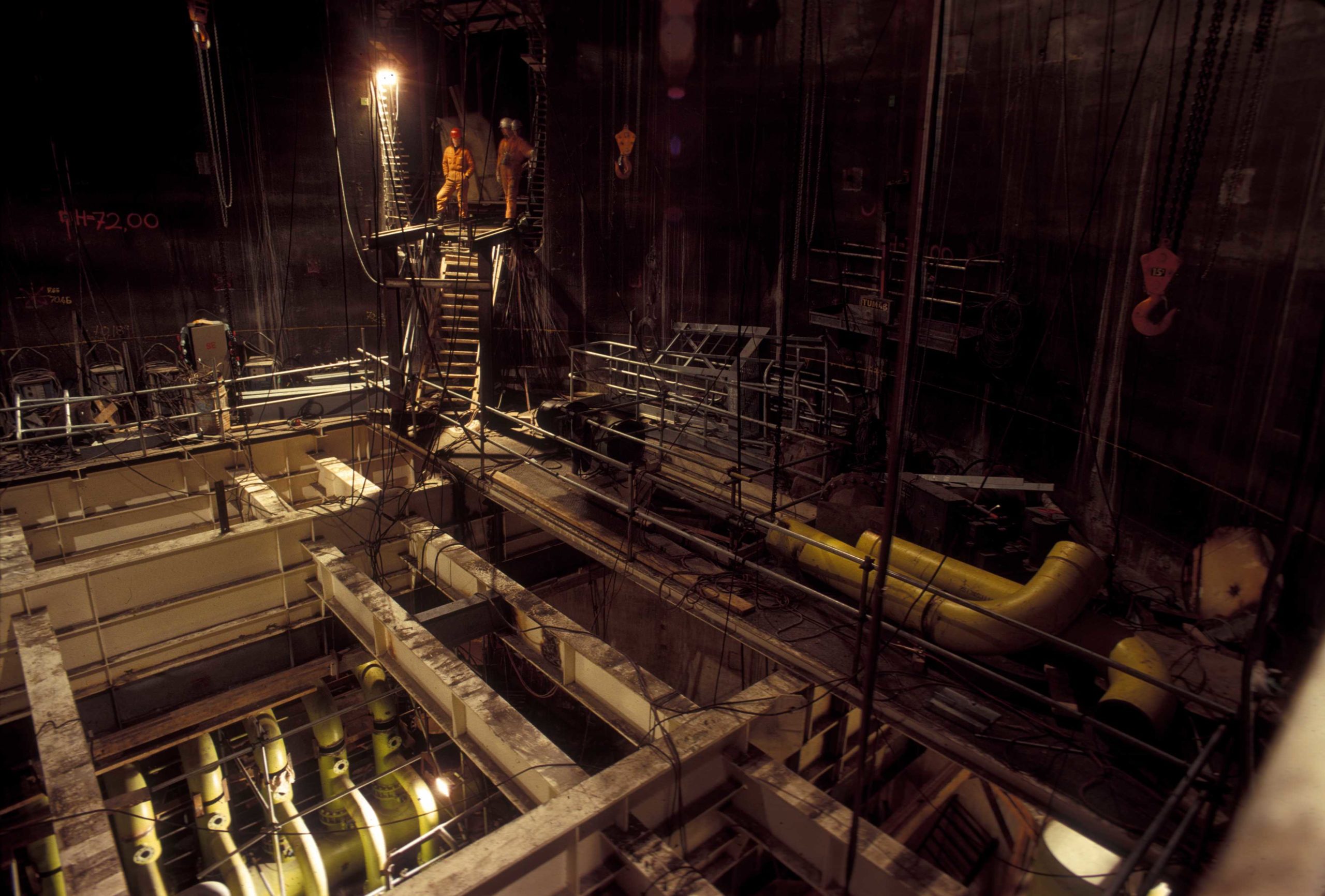 Statfjord A,
 Statfjord A,
 Bygging av A-dekket,
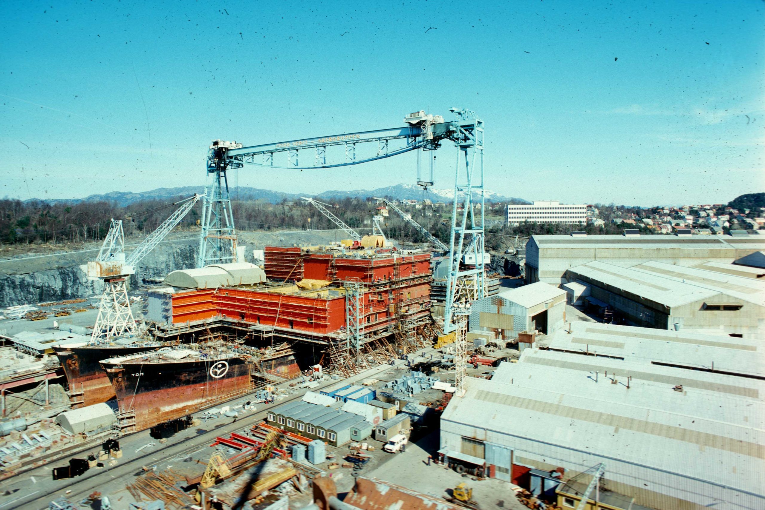 Bygging av A-dekket,
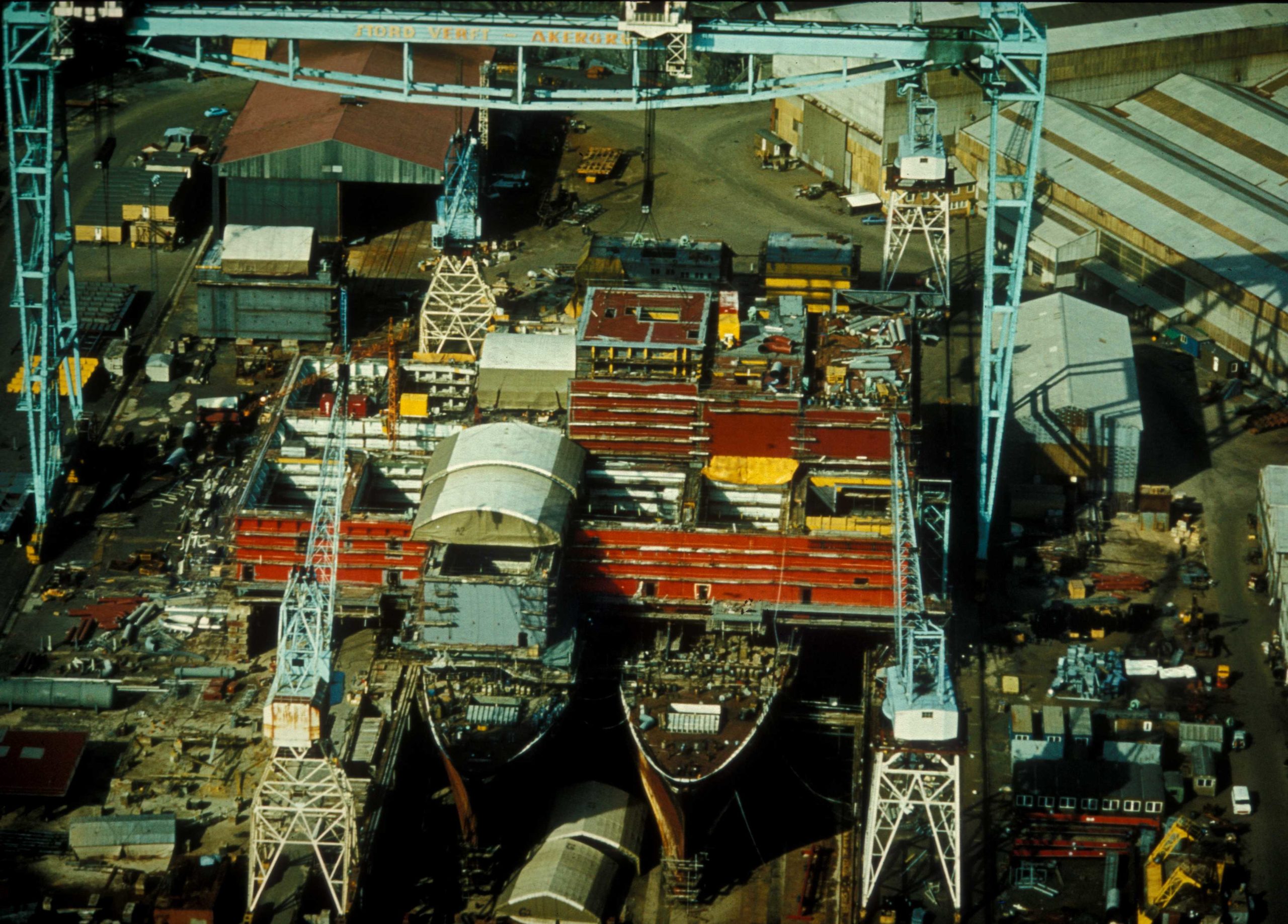 Bygging av A-dekket,
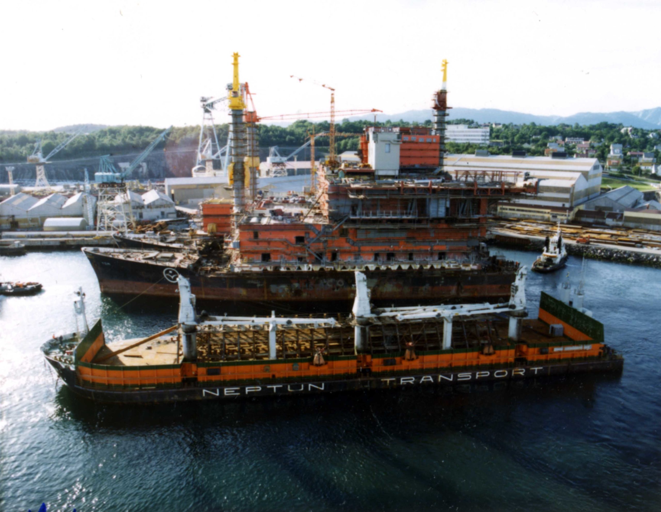 Bygging av A-dekket,