
Platform utilities

Chemicals
 hjelpesystemer, engelsk,
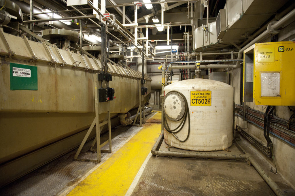
Many different chemicals and chemical compounds are used on the Statfjord platforms for such purposes as separating oil and water. Other applications include inhibiting or breaking down oil droplets in the produced water (emulsions), which is separated from the crude oil flow. Chemicals also prevent or stabilise foaming, or inhibit hydrate (hydrocarbon ice) formation, bacterial growth or corrosion. These substances are shipped out to the platforms on supply vessels. Among the commonest are the following:
Methanol is used to prevent the formation of hydrate plugs in pipelines, which can halt liquid flow. When gas contains small quantities of water, ice-like clumps can form under special pressure and temperature conditions.
Glycol primarily serves an agent for removing water from rich gas because it acts as an efficient absorber of water. It is also used in coolant systems to reduce the freezing point to -12°C.
 hjelpesystemer, engelsk,
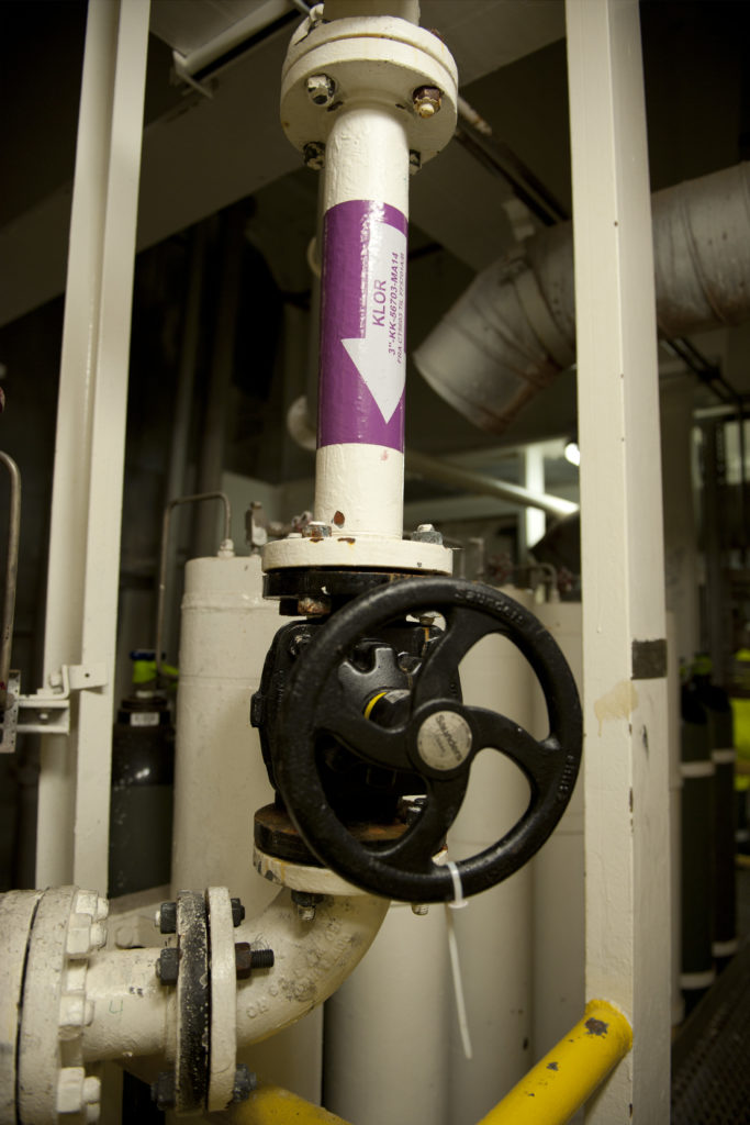
Chlorine can be added to seawater to prevent the growth of bacteria in pipelines and ballast water, seawater and fire water systems. Sodium hydrochlorite (NaOCI) or bleach is used to kill unwanted organisms.
Corrotion inhibitor is added to prevent internal corrosion in piping and tanks. The substances used are usually based on organic compounds which form a protective film on metals.
Fuel
 Statfjord C, hjelpesystemer, engelsk,
Two types of fuel are needed on the platforms – helicopter (aviation) fuel and diesel oil for power generation and other specialised machinery.
Supplies are brought in by ships equipped with special tanks for helicopter fuel. These can also pump diesel oil directly via hoses to special storage tanks in one of the cells of the concrete gravity base structures (GBSs).
Lubricating oil
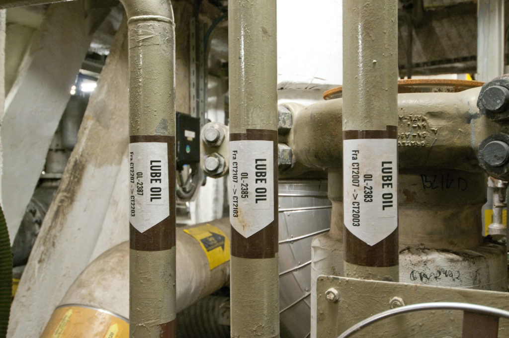
This system distributes various types of lube oil to the main systems through a permanent piping network.
 hjelpesystemer, engelsk,
From the filling (tote) tanks, they are piped via lube oil distribution tanks to the most important consumers – gas turbines, generators, water injection pumps and fire pumps.
Other types of oils/lube oils are also required on board, but the level of consumption does not warrant a fixed distribution system for them.
 Statfjord A, hjelpesystemer, engelsk,
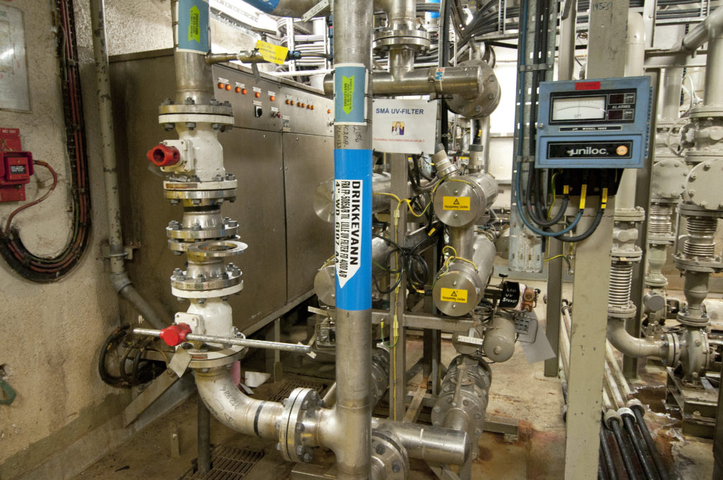
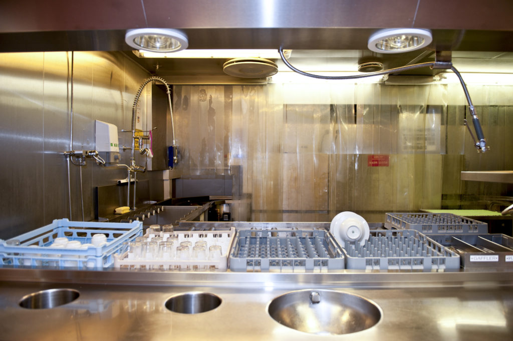
Potable water is produced for use in the living quarters and selected areas of the platform. Desalinated water is pumped from one of the storage tanks via ultraviolet sterilisation units to consumer tanks located on the roof of the living quarters.
 hjelpesystemer, engelsk,
 hjelpesystemer, lasting,
Cranes
Cranes on the platform are used for:
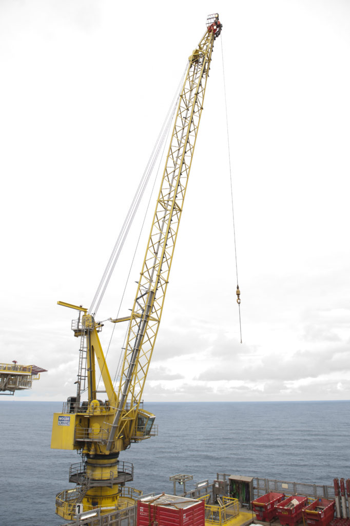
- lifting from or discharging to supply ships
- maintenance and construction lifting over the whole platform and in the equipment shaft
- handling pipes and equipment.
Bulk handling
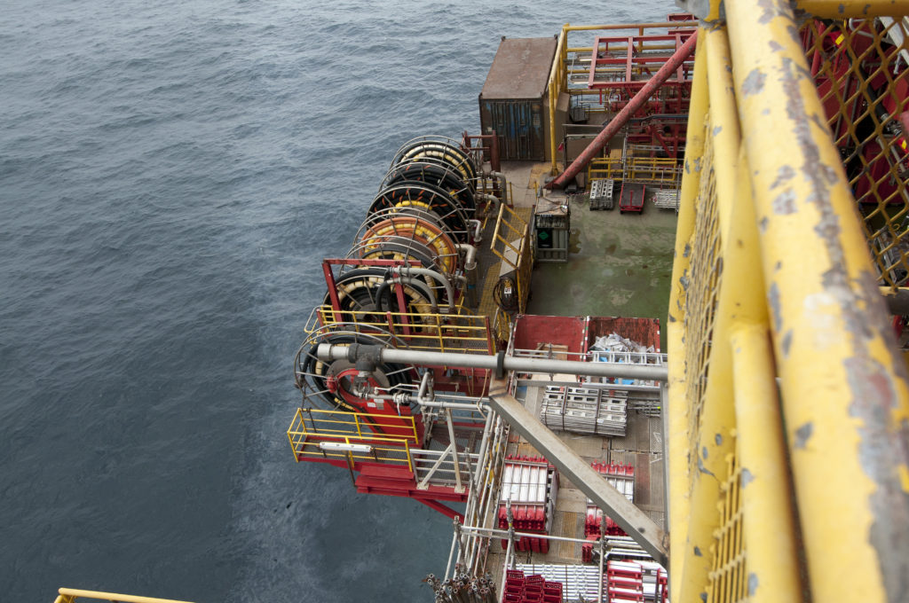
Equipment for bulk handling is used to transport, handle and store various liquids, powders, gases and chemicals required for the platform’s process system and utilities. These products are brought out by supply ships and transferred to the platform either in tanks or via hoses.
Tanks and other bulk containers are lifted by crane from the supply ship to the platform’s storage area on the open deck. Liquids used in large volumes are transferred via permanently installed piping to the fixed storage tanks. Empty tanks are discharged for transport to land.
Diesel oil, fresh water, barytes, gel and cement are transferred to the platform’s bulk storage tanks with the aid of hoses lowered to the supply ship.
Power supply
The electrical system on the platform provides all normal and emergency power supplies.
 hjelpesystemer,
Main electricity is supplied by three 19-megawatt generators as 13.8 kilovolt, three-phase 60 Hertz current. The generators are driven by gas/diesel turbines.
Flaring and atmospheric ventilation
Hydrocarbons are found under varying pressure and temperature on large parts of the platform. For practical and safety reasons, some of the gas can be led to a safe place for flaring.
Process control monitors and controls all systems on the platform to ensure that hydrocarbons can be produced as safely as possible. The main functions involve:
- maintaining a check on data transmission between the production system and the control-room terminals
- analogue operating commands
- automatic switches and logical sequence control commands
- alarm logging
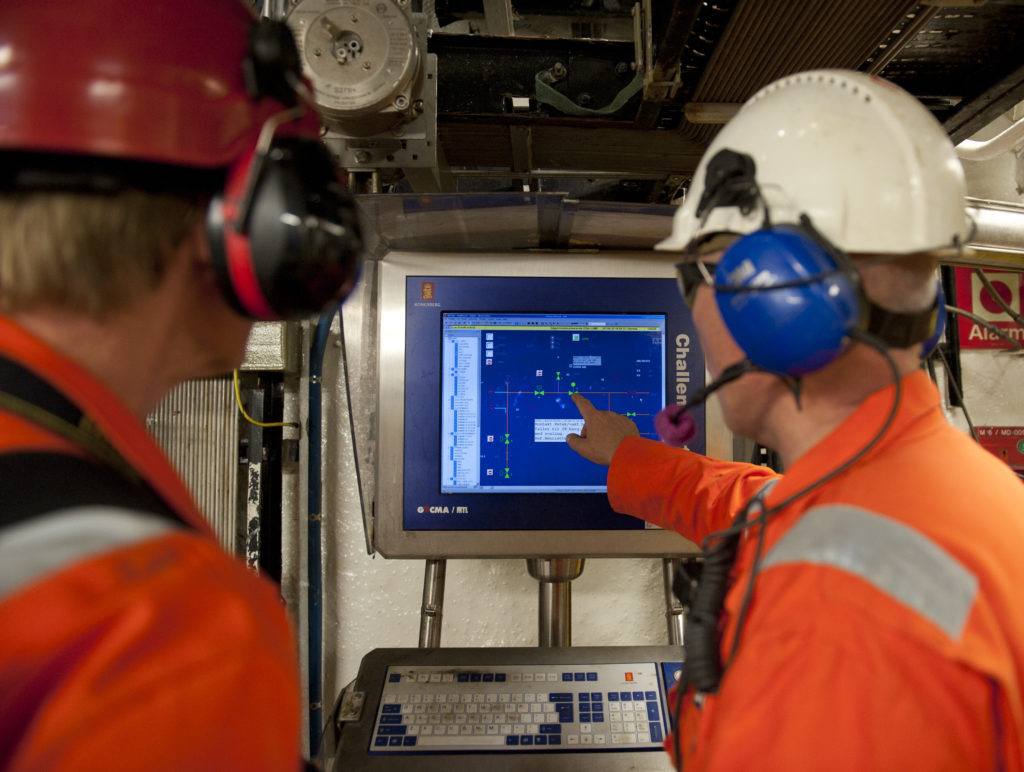
All this information is monitored from a central control room. Printers and displays for alarms and trends are also concentrated there to provide the operators with a good and accurate picture of conditions at all times.
 hjelpesystemer, engelsk,
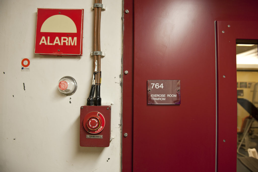
Safety monitoring is a system intended to handle “all” aspects of safety on the platform. Field instrumentation and sensors for fire and gas alarms monitor the whole process and every module.
The purpose of the system is to initiate emergency shutdown of production when the process monitoring system fails to handle the problems which might occur. In principle, it comprises two systems:
1. The process shutdown system monitors the process and shuts it down if control is lost, and thereby prevents the plant being operated in a hazardous manner – under pressures higher than the tanks are designed to handle, for example.
2. The emergency shutdown system, which reacts if hazardous conditions arise – such as a gas leak or a fire. This system receives signals from fire and gas detectors as well as from manual alarms.
The metering system for production and consumption meters the quantity of gas and oil exported from the platform as well as the amount of consumption and fuel gas used internally. This system attracts great attention from all levels of the organisation, since its measurements form the basis for the revenues generated and the tax to be paid on output.
Safety and security
 hjelpesystemer, engelsk,
Systems in this category are required for notifying and executing actions to prevent or reduce major or minor damage. They also include systems for emergency evacuation or for retrieving people who have fallen into the sea.
 hjelpesystemer, engelsk,
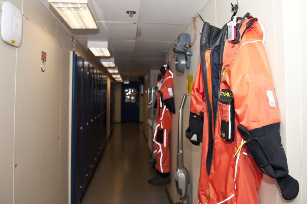
Rescue/safety equipment
This is intended to permit speedy evacuation of personnel from the platform in an emergency, or to retrieve people who have fallen overboard. It includes:
- covered free-fall lifeboats
- covered rafts which inflate on contact with the sea
- man-overboard boats (MOBs)
- chutes for evacuation to the sea
- personal survival suits.
Communication
 hjelpesystemer, engelsk,
Rapid advances have been made in this area since Statfjord came on stream. The following
thereby describes both the original position and the current systems.
External communication
These systems provide the necessary links between the platforms and contacts on land, at sea and in the air.
1980
The satellite system installed on Statfjord A was intended to the main carrying channel for communication between the field and the Norwegian mainland. Communication
to/from the B and C platforms was relayed over line-of-sight microwave links to Statfjord A for onward transmission. Were the satellite system to go down, VHF and MF radio communication would take over. An emergency phone system provided direct communication with land.
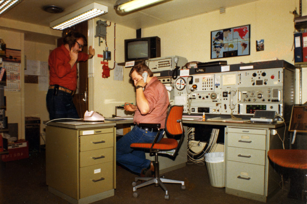 hjelpesystemer, engelsk,
The radio shack on the A platform kept in touch with helicopters via VHF (AM) radio and with ships via VHF and MF communication. Crane drivers could communicate directly with ships using VHF radio-telephones operating on the marine frequency.
A telemetry system linking the platforms was designed for fail-safe operation during transfer of crude oil between the installations. The control room on each platform monitored and coordinated the oil pumps. This system also had a speech channel for communication between the control room and the loading buoy/shuttle tanker.
Walkie-talkies were used where phones were impractical. This system provided a back-up for the phone network, the public address system and ship-to-ship communication.
The internal phone system was operated from the radio shack. This was also the location for the telex system, which was operated via the satellite link.
 hjelpesystemer, engelsk,
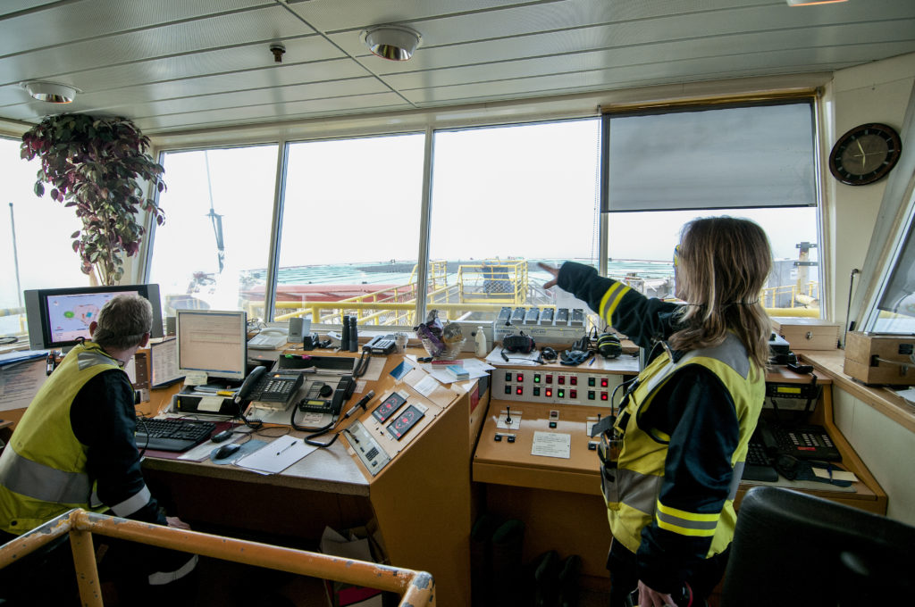
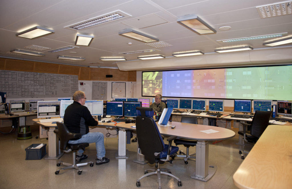
Control room
The control room is placed in a secured area, where process operators monitor and control the various process and service systems. Two
separate monitoring and control systems are provided:
- a control and information system for safe operation and shutdown, with a duplicated control system for ballast tank level
- a supervisory control and data acquisition (Scada) system which monitors and checks production, drilling, transport and other connected processes.
Process data are read off automatically by the system to provide the basis for dynamic process diagrams and tabulated reports presented to the operators. Possible changes to the status of a monitored process are presented as colour changes on the displays.