
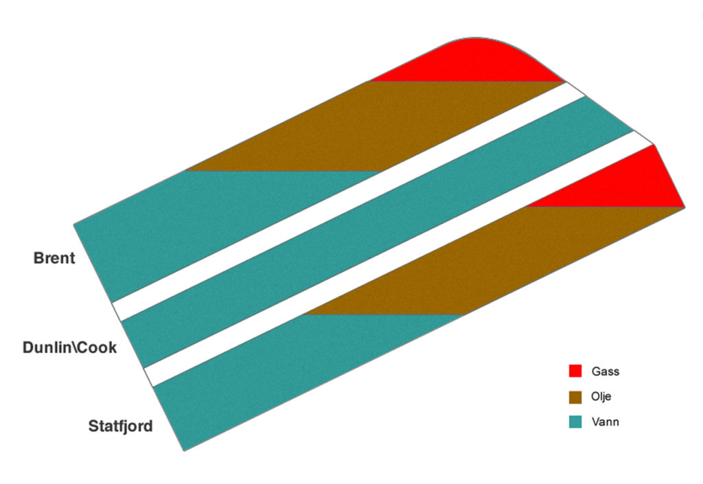
Geology and reservoir

Containing 75 per cent of the stock tank oil originally in place (Stooip), Brent is the uppermost component. The Statfjord formation is the lowest, with 24 per cent of the Stooip. Sandwiched between them, Dunlin contains almost no hydrocarbons. The three formations are separated by layers of impermeable shale. Oil from both Brent and Statfjord is very good quality, with a low sulphur content. Recoverable reserves originally present in the field are put at 3 570 million barrels of oil, 80 billion standard cubic metres (scm) of gas, 20 million tonnes of propane and butane (natural gas liquids – NGL) and 6.3 million barrels of condensate (light oil). Hydrocarbon-bearing strata in Brent and Statfjord were deposited in the middle Jurassic and the lower Jurassic/upper Triassic respectively – in other words, about 170-210 million years ago. The structure containing these reservoirs is tilted six-seven degrees towards the west and bounded on the east by a system of faults. The cap rocks keeping the oil and gas in place are upper Jurassic/Cretaceous shales.
The Brent group comprises sandstones and is divided into five smaller formations, which are grouped in turn into the upper and lower Brent. Permeability – how easily the oil and gas flows through the rock – is best in the Tarbert and Etive formations, while average porosity – how much of the rock is made up of pore spaces – is very good. The Statfjord formation, moving from the bottom up, contains a mix of sandstone, siltstone and shale. Divided into three zones, its porosity is generally good but permeability is best in the upper part of the Nansen zone.
 geologi og reservoar, illustrasjon
Initial production strategy
During the first 28 years of production from Statfjord, the strategy was to maintain reservoir pressure with the aid of water or gas injection while draining the main field structure. Water injection began in the upper and lower Brent in 1981 and 1982 respectively. This was assisted by water alternating gas (WAG) injection from 1997 until 2008, when Statfjord late life production began. Production wells were placed in the uppermost part of the formation’s eastern section. Before the gas export pipeline became operational, associated gas produced with the oil was injected back into the Statfjord formation. Oil production was kept at a high level to provide space for this gas. The gas began to be exported in 1986 via Statpipe and the British Flags pipeline. To compensate for the loss of pressure support from injecting gas, water injection combined with WAG was also initiated in the Statfjord formation in 1997. As time passed, the challenge became to drill new production wells in order to tap pockets of oil further to the east, where the field was broken up by small faults.
Other fields phased in
As Statfjord output declined, spare processing capacity became available on the platforms which could be used to process production from nearby fields. As a result, the Snorre A platform has been tied back to Statfjord A while the Statfjord North, Statfjord East and Sygna satellites are linked to the C platform.
Statfjord late life
The production strategy on Statfjord has been revised in order to extend the field’s producing life. All available gas is to be recovered by reducing reservoir pressure. Named the Statfjord late life project, this new approach is intended to improve recovery factors from 53 to 74 per cent for gas and from 65 to 68 per cent for oil. At the same time, the field’s producing life will be extended by 20 years to 2030. This solution was approved by the partners and the government in 2005, and was implemented for the Statfjord formation in 2007 and for the Brent group in 2008. Roughly 80 wells are due to be drilled or recompleted as part of Statfjord late life. Many of these wells will be sidetracks drilled from existing wells to tap new areas of the reservoir. In order to produce at lower reservoir pressure, both gas lift and sand control are needed in virtually all the wells. Downhole electric pumps will be installed towards the end when gas lift ceases to function. A new Tampen Link pipeline runs from Statfjord B to tie into Britain’s Far North Liquids and Associated Gas System (Flags) in order to export the greater gas volumes to St Fergus in Scotland.
Kilder:
Main considerations in develoment of Statfjord Field, H. Ager-Hansen, Statoil and J. Medley, Mobil
Statfjord Field: Field and Reservoir Management Perspectives, Atle Aadland, Olav Dyrnes and S.R. Olsen, SPE and O.M. Drønen, Statoil A/S. SPE Reservoir Engineering , August 1994
Increasing economic recovery by synergetic development of neighbouring fields in the Norwegian Continental Shelf. Adolfo Henriquez, Øystein Arvid Håland, Stein Børre Torp (Statoil) 2001
Turning a North Sea Oil Giant into a Gas Field – Depressurization of the Statfjord Field, R. Boge, SPE, S.K.Lien, A. Gjesdal and A.G. Hansen, SPE, Statoil. SPE 96403 2005
The use of sea water tracer as a tool for history matching of the Statfjord Fm simulation Model. Master Thesis, Henriette Strøm, 2010
Triassic lithostratigraphy of the Northern North Sea Basin. Kjell-Sigve Lervik – Norwegian Journal of Geology 2006

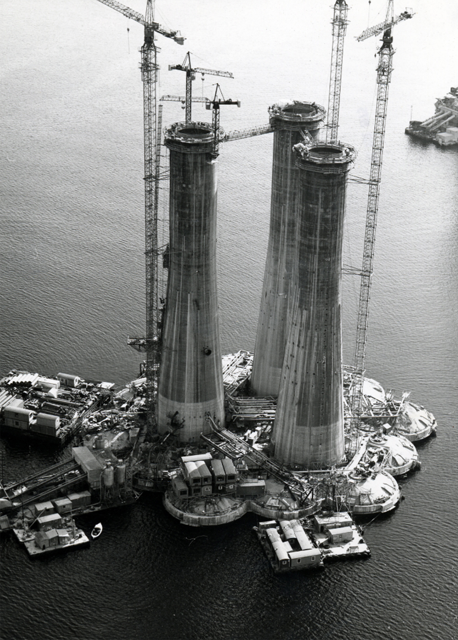 støping av a-en,


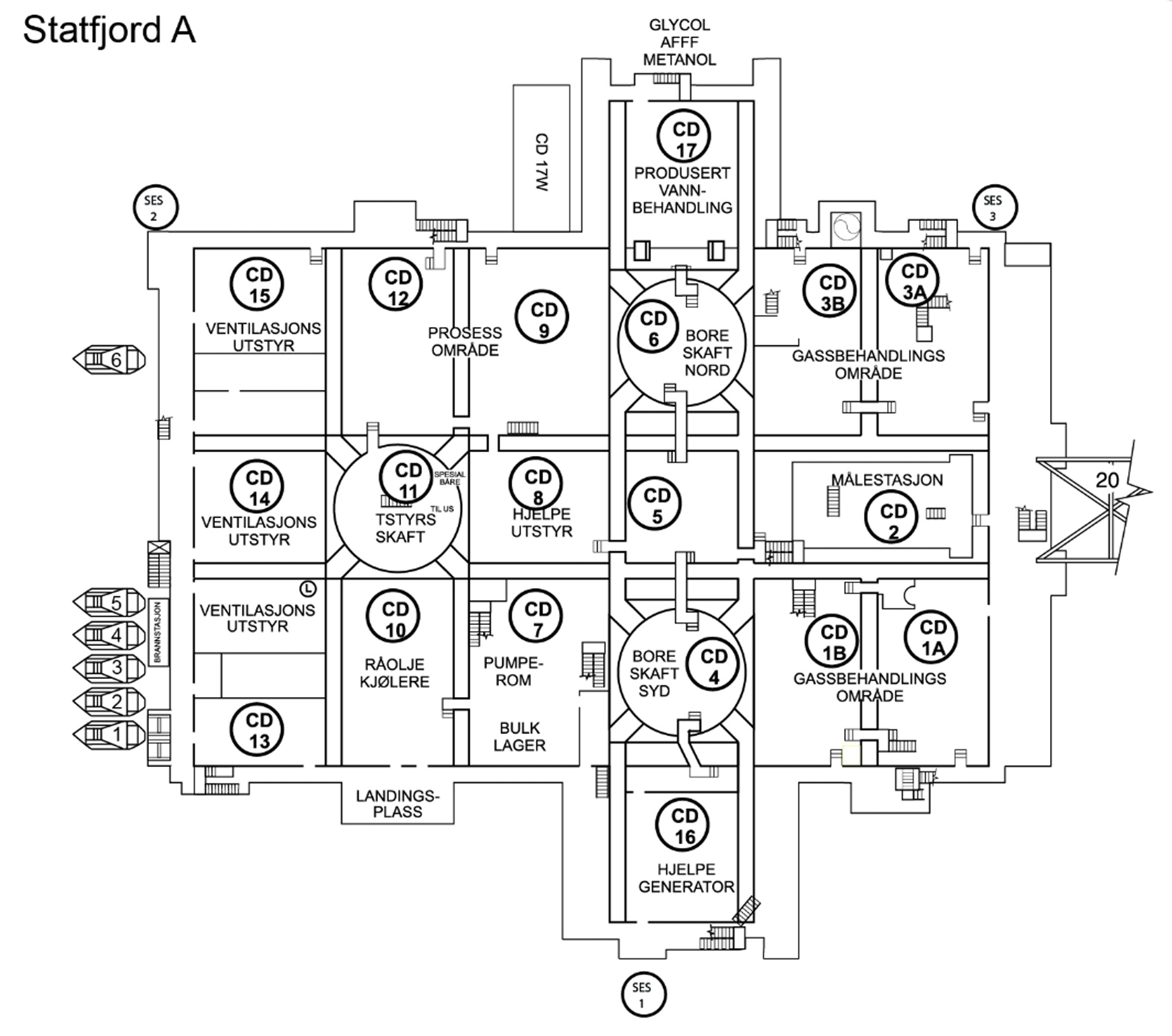 Statfjord A,
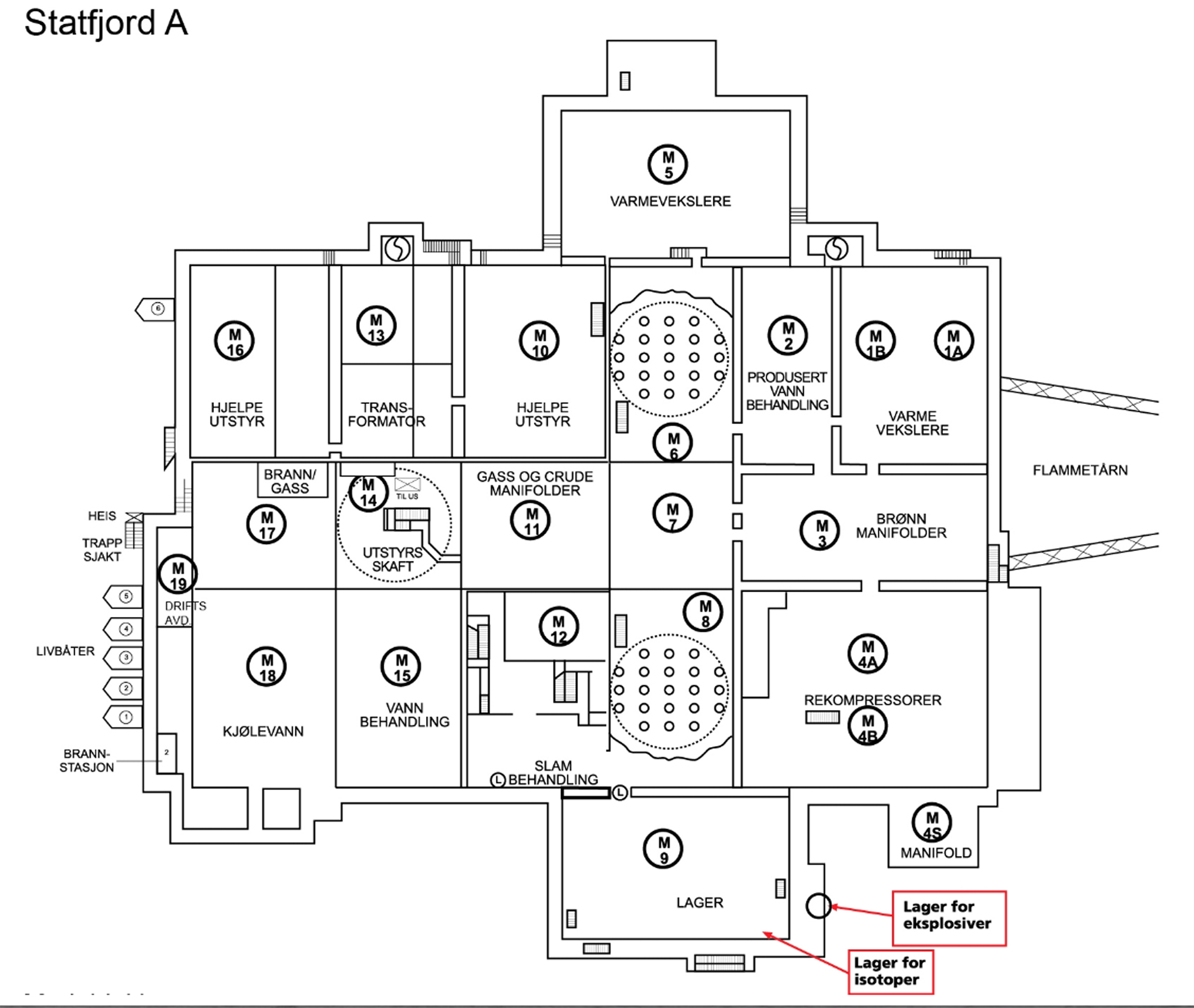 Statfjord A,
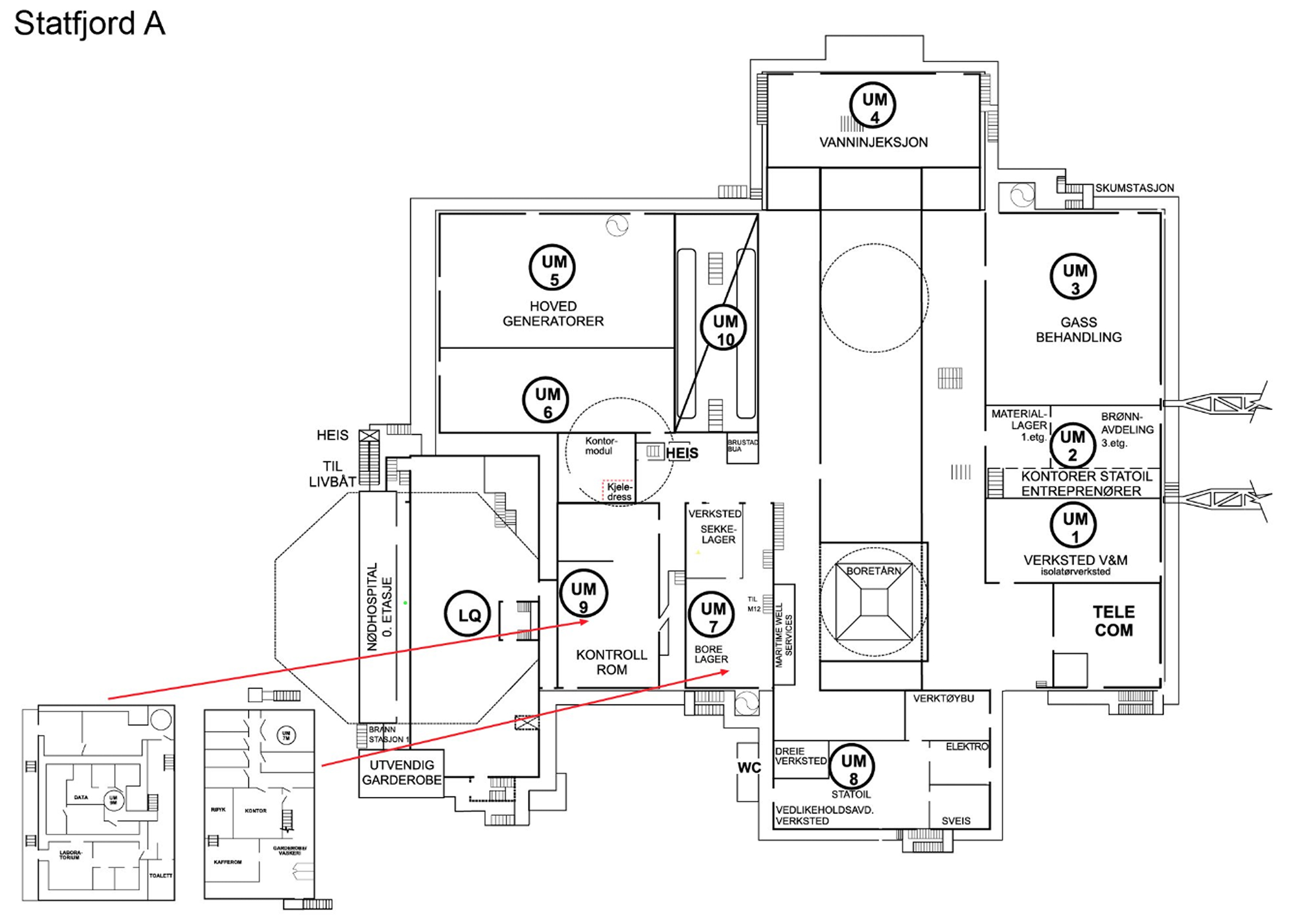 Statfjord A,
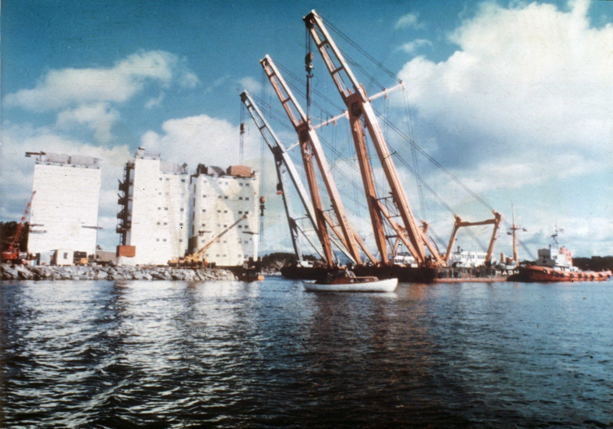 Bygging av A-dekket,
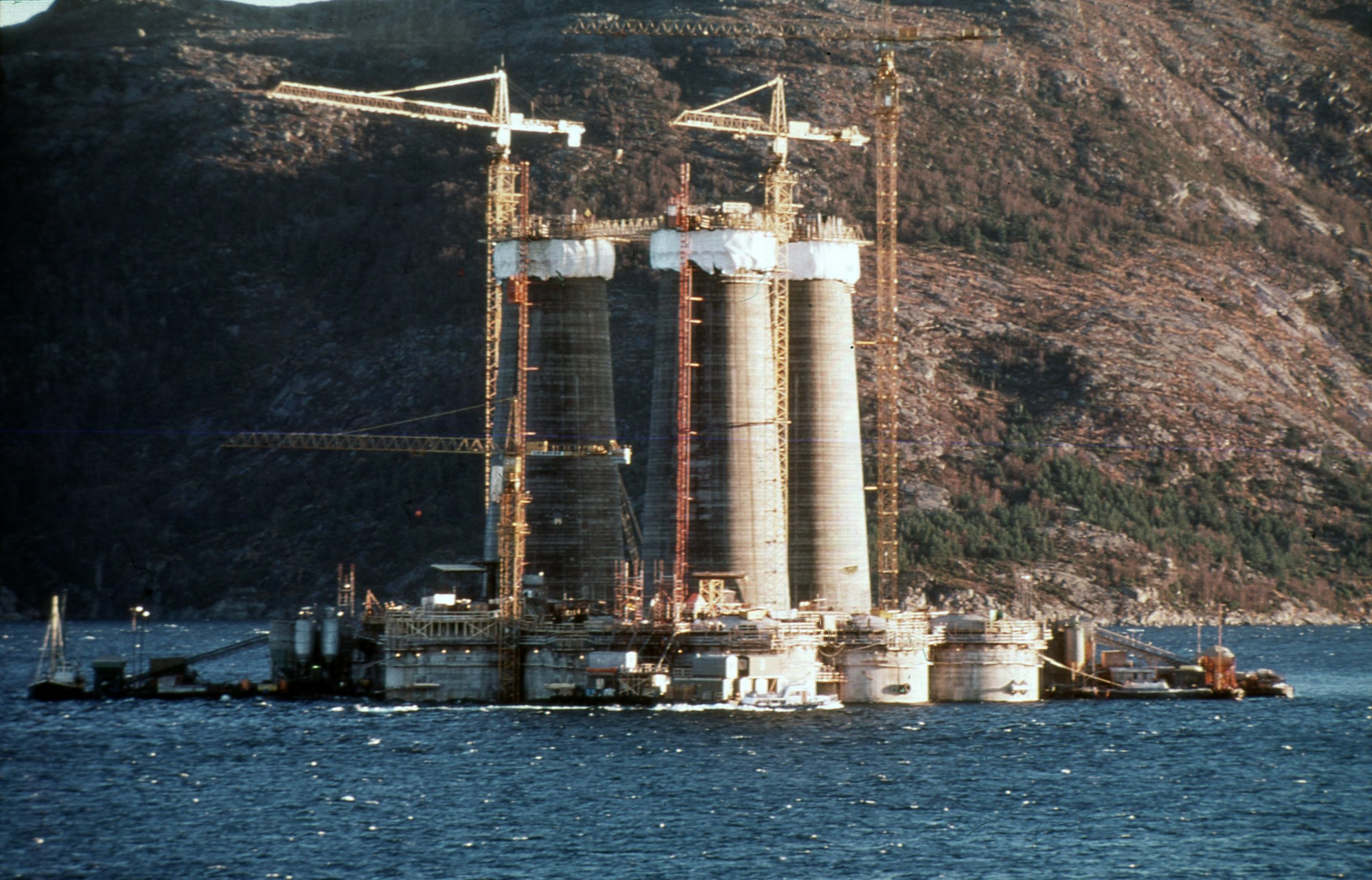 støping av a-en,
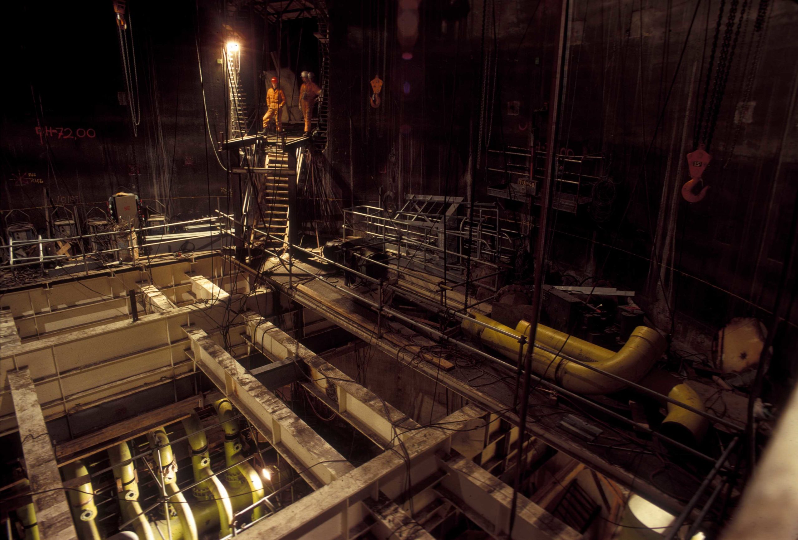 Statfjord A,
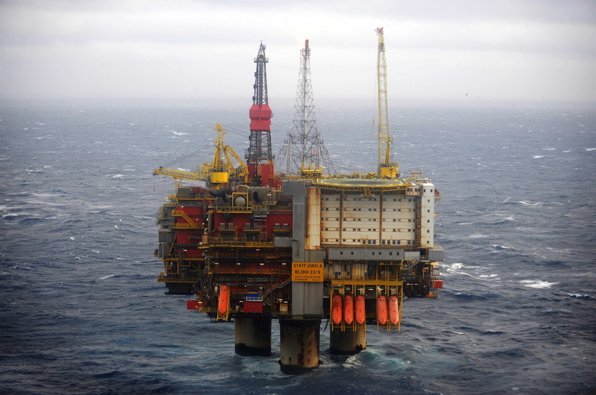 Statfjord A,