
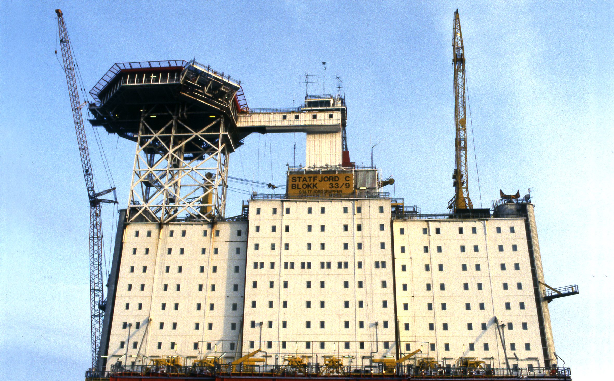
The Statfjord C platform

The GBS was built by Norwegian Contractors at Hinnavågen in Stavanger, and the integrated steel production, drilling and quarters (PDQ) topside by Moss Rosenberg Verft at Buøy in the same city. Standing in 145.6 metres of water, the platform is located at 61° 17’ 47.696” N and 1° 54’ 09.151” E. Its total height from seabed to the top of the drilling derrick is 280.4 metres.
Design production is 210 000 barrels of oil per day plus associated natural gas. The concrete cells in the GBS can store 1.9 million barrels, while the transfer capacity to shuttle tankers is 50 000 barrels per hour.
The concrete structure comprises 24 cells, of which 19 are used for oil storage and one for diesel oil. The remaining four are extended to form the shafts which carry the topside. Two of the shafts are used for drilling, each with 21 slots, one for utilities and one for risers.The topside comprises a module support frame (MSF) with equipment for gas treatment and utilities. Specially outfitted modules are placed on the MSF. The living quarters hang from the outside of the MSF, with the helideck on their roof. For safety reasons, the large flare boom is attached to the side of the MSF opposite the living quarters.
Statfjord C is connected to the C-SPM loading buoy. Two subsea installations were also tied back to the platform to produce oil from the north flank of the reservoir in 1999. Statfjord G handles oil output, while Statfjord H is used for water injection.
The loading buoy was shut down in 2005, and is due to be removed during 2012. Production from Statfjord is currently exported via the OLS-A and OLS-B buoys.
Statfjord C is also equipped to process production from the Statfjord East, Statfjord North and Sygna satellites.
Major conversion work was initiated on the platform in 2005 for the Statfjord late life project, which is intended to increase gas production by more than 20 per cent while extending the field’s producing life by at least 10 years.
Process equipment
Wellstreams are conducted to a separation facility where gas, water and sand are removed from the oil. Four separation stages are used to process and stabilise crude until it is suitable for export. This oil is conducted to the storage cells for pumping across to shuttle tankers.
Gas produced through the separation process is compressed and dewatered before being piped to land at Kårstø in Norway or St Fergus in the UK. Natural gas liquids (NGL) – propane and butane – are removed at these receiving terminals before the gas is sent on to markets in the UK and continental Europe. Before 2007, some of the gas was also compressed to a higher pressure and injected back into the reservoir via dedicated wells for this purpose.
 C-plattformen,
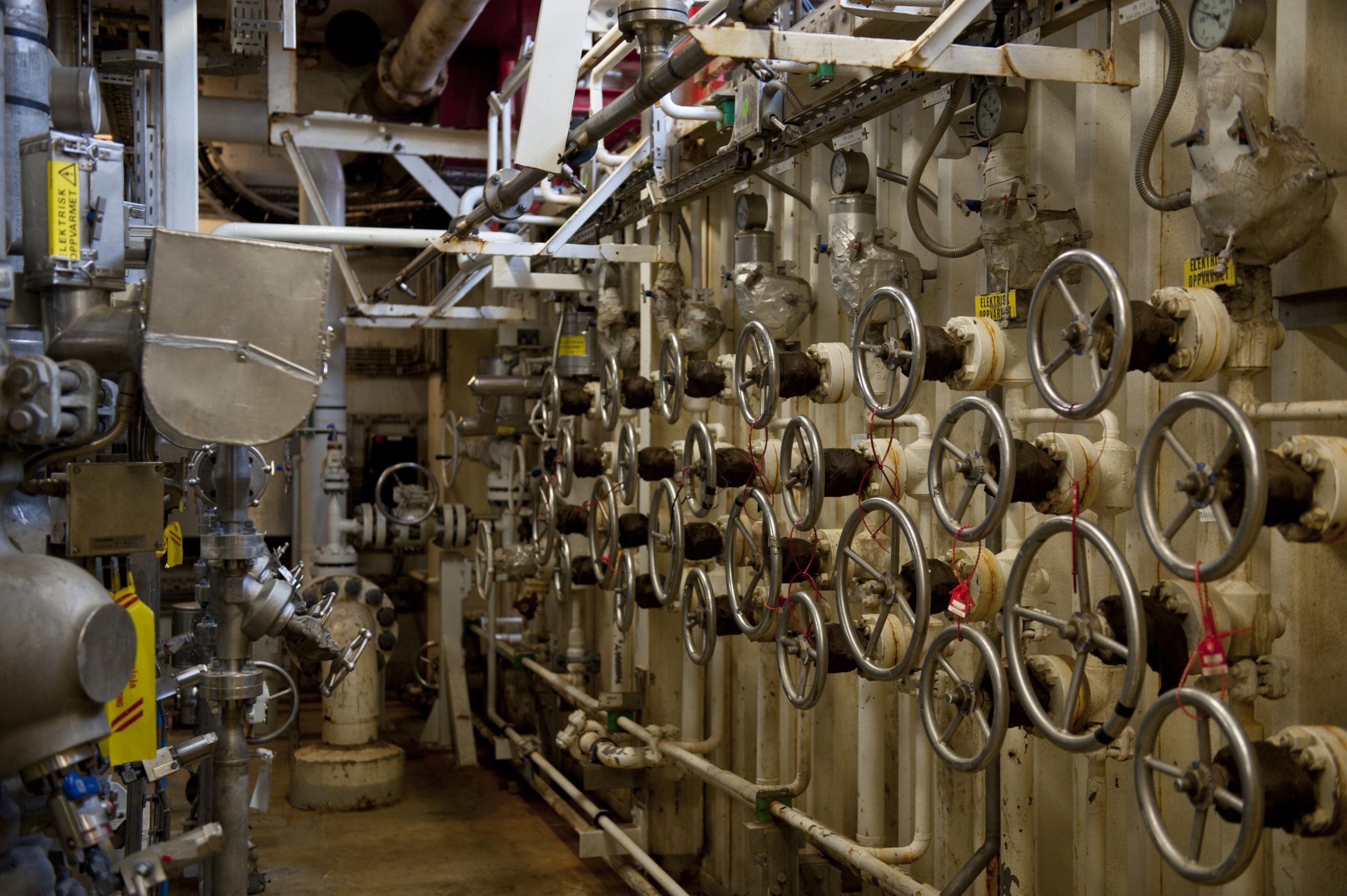
Utilities
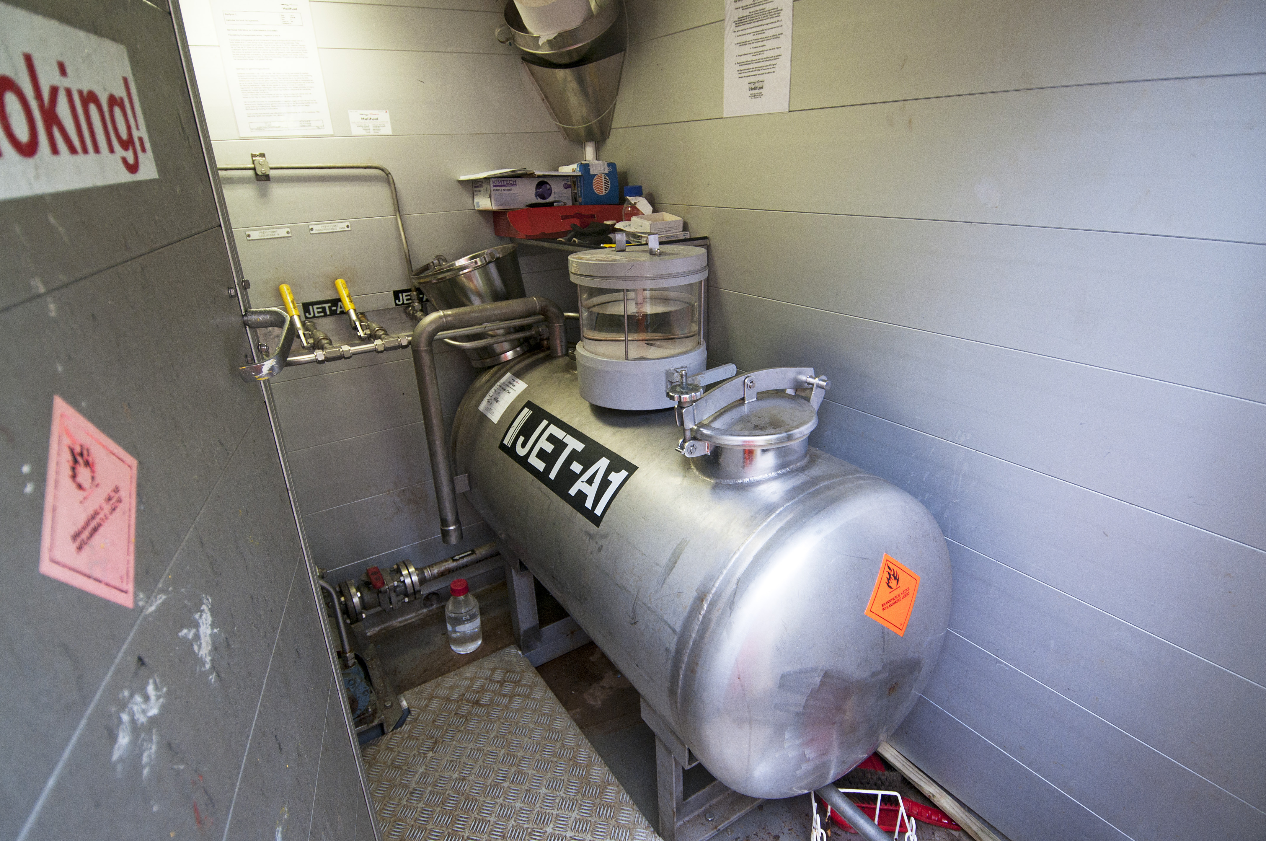 hjelpesystemer, jet fuel, engelsk, C-plattformen
The utilities perform necessary services related to operation of the production processes and essential functions on Statfjord C. Examples include drinking (potable) water, coolant water, sewage systems, helicopter fuel, air conditioning, process chemicals, power supply, communication, etc. These systems are more extensive than the production facilities. With a great deal of liquid in circulation, much supervision by the operator is required.
Drilling rig
The drilling rig embraces the blowout preventer (BOP) deck, the drill floor, the derrick and skid rails. Hydraulic jacks are used to position the derrick over the relevant well. A mud processing unit (MPU) is installed on the south side of the derrick and skidded together with the latter.
Topside
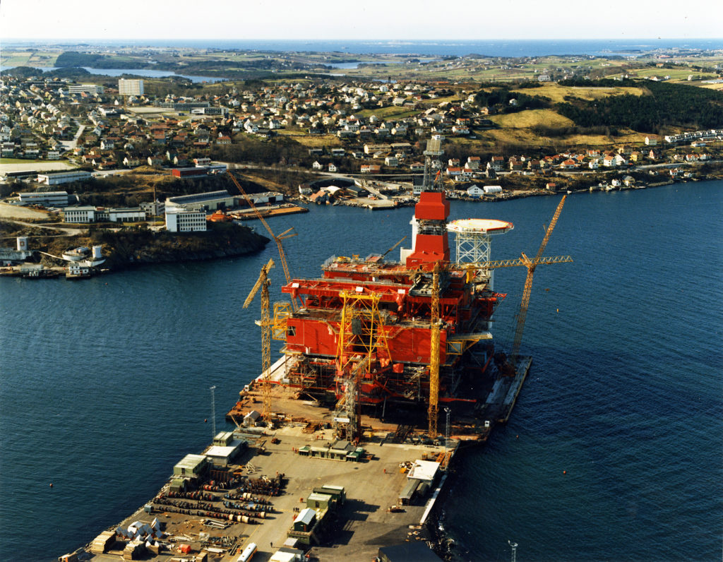 Statfjord C, engelsk, bygging,
The MSF is a steel latticework construction comprising four longitudinal and six transvers beams. It is 114 metres long by 55 metres wide, giving an area of 6 270 square metres.
Total topside space on Statfjord C is 28 900 square metres. Three separate main decks are provided – cellar, module and weather.
Cellar deck
This provides space for heavy equipment, such as tanks, coolers and separators. Storage tanks for desalted water and diesel oil hang beneath the deck. The flare boom extends from the eastern end of the cellar deck, a position which places it as far as possible from the living quarters, the helideck and the air intakes to the main gas turbines. Lifeboats and liferafts are positioned at strategic points around the cellar deck.
This comprises 13 separate modules, with the drilling and main process facilities located at its eastern end. Utilities are placed in the western half of the deck, and separated from the process equipment.
Weather deck
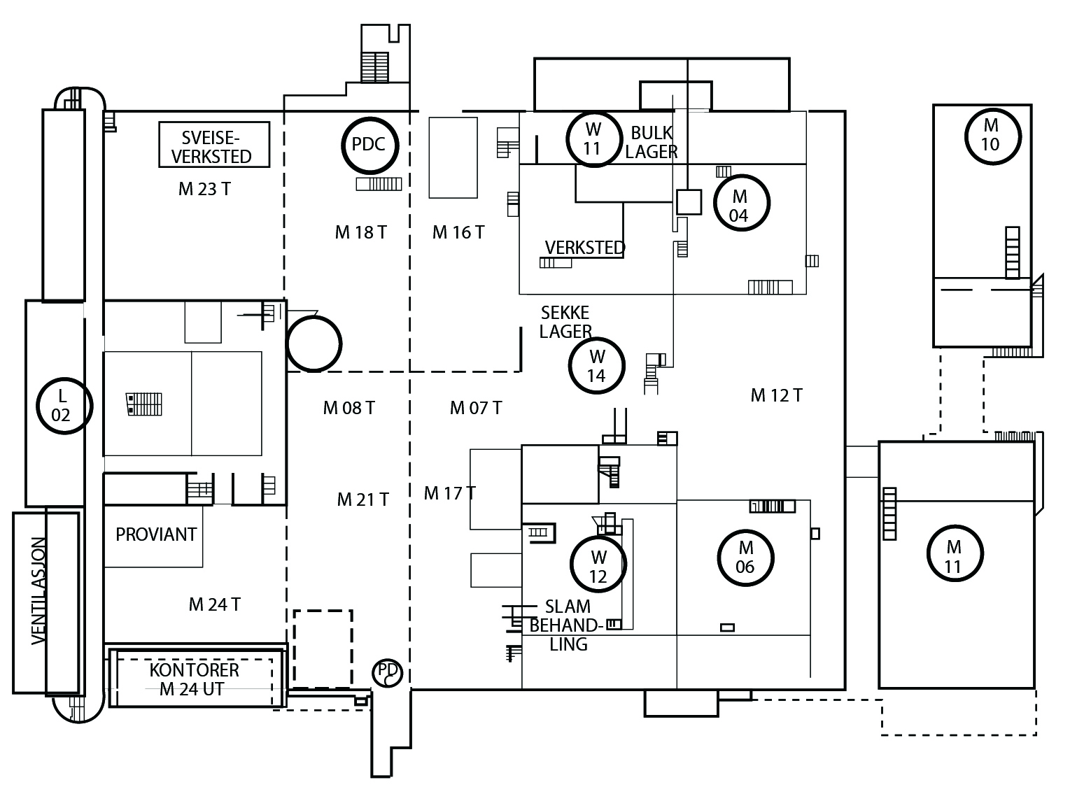 C-plattformen,
This consists largely of the roofs of the structures installed on the module deck. In addition comes a separate module which serves as a store for drilling equipment. The large open surfaces are used for storage and as handling spaces for equipment being load onto or discharged from supply ships.
Upper weather deck
This comprises the helideck and the roof of the module for drilling equipment storage.
Living quarters (LO)
 c-plattformen,
The living quarters are positioned on the western edge of the topside and divided into four modules – south (L01), centre (L02), north (L03) and the service area (L04) located above the central control room (CCR) in area C14. The helideck stands in the north-western corner above section L03. Outfitted with double cabins, the LQ can accommodate 278 people with associated canteen and public rooms. Its modular structure extends over nine stories. The radio shack, communication control room and arrival/departure hall are on the eighth floor.
Two lifts and internal stairs link the stories. Emergency stairs and external escape routes lead directly to the lifeboat and liferaft stations.
GBS
 Statfjord C, bygging, engelsk,
The concrete GBS is a four-shaft Condeep with 24 storage cells in a concentric formation. Each cell has an inner diameter of 23 metres and is 64 metres high. One cell contains an internal tank for diesel oil, with the gap between the inner and outer walls providing storage for drilling mud. Four of the cells are extended to form the shafts which carry the MSF. The shafts rise 105.6 metres above the cells, with the underside of the MSF 29 metres above the sea surface. The utility shaft houses such equipment as loading pumps for crude oil and systems for ballast control. It contains 13 deck levels.