Loading buoys – various solutions

person Finn Harald Sandberg, Norwegian Petroleum Museum
Loading buoys are a collective term for facilities used to transfer (load/discharge) liquids between different units, at least one of which is floating. Many varieties of such structures exist. These include catenary anchor leg mooring (Calm) designs and single point moorings (SPM), which comprise columns or towers fixed to the seabed. Some examples used on the Norwegian continental shelf (NCS) are presented below.
— One of Gilf Tide's two "CALM"loading buoys. Photo: Magne Vågslid/Norwegian Petroleum Museum
© Norsk Oljemuseum

CALM – Catenary Anchor Leg Mooring

One type of Calm is presented in the figure above. This was the design used on Ekofisk in the Norwegian North Sea until a pipeline had been laid to transport the oil to Teesside in the UK. The flowline from the storage facility is conducted through a pipeline end manifold (PLEM), where it converts into a flexible hose (or two, as in the drawing). This then connects to the actual buoy.
 A separate floating hose from the latter is connected manually with the aid of a small boat to the tanker, and conducts the oil into its tanks.

The availability of these buoys in the North Sea was below 50 per cent – they were originally designed for use in very different conditions.

Statfjord A – SPM/ALP

The SPM selected for Statfjord A comprised a latticework column, as illustrated to the left. It was built by Kværner Egersund south of Stavanger and installed on the field in 1975.

A flowline connected the platform to the base of buoy, where a universal joint formed the transition to the riser in the centre of the support column. This joint made it possible for the column to oscillate in all directions, depending on current and wave conditions – hence the name articulated loading platform (ALP).

In order to hold the column in a more or less vertical position, large buoyancy tanks were installed both at its base and just beneath the sea surface. The loading flowline was led out to the transfer boom ­– another latticework structure, which was part of the rotating head placed on top of the column ­– and connected to a flexible hose. A helideck was also installed on the head, along with basic accommodation for crew performing periodic inspection and maintenance.

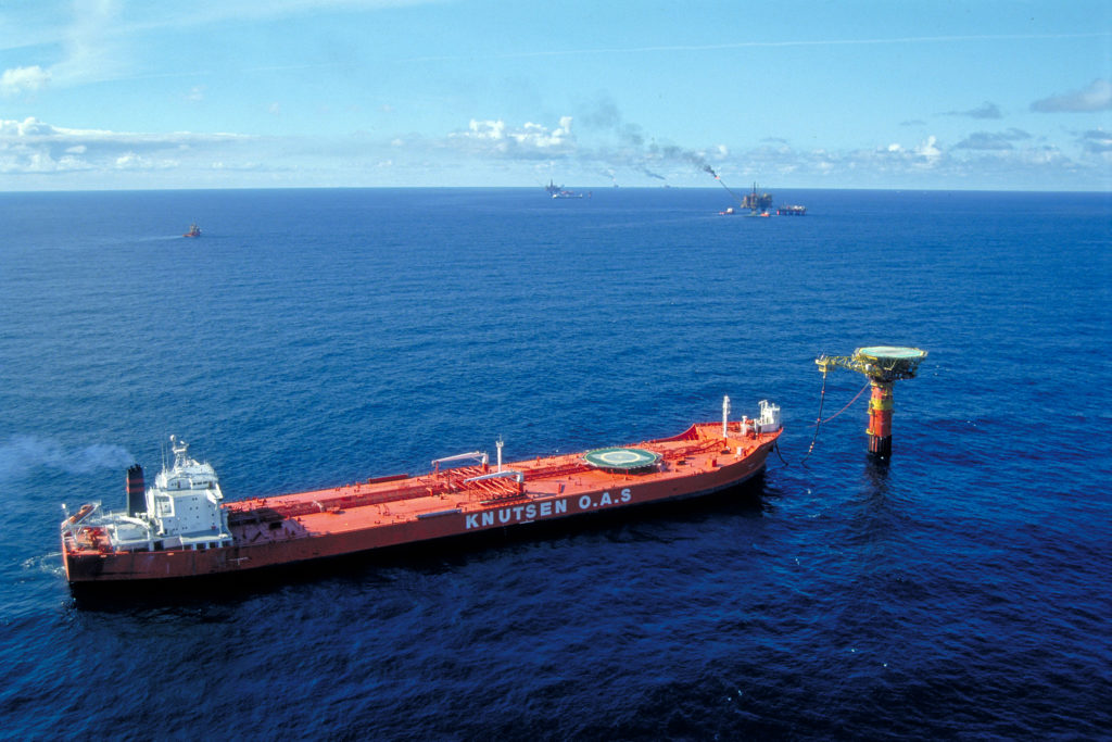
A simple arrangement made it possible to moor a tanker and connect the loading hose under control from the vessel’s bridge. The hawser initially had to be kept taut, but this requirement was dropped as the vessels were equipped for dynamic positioning.

lastebøyer ulike alternativ, engelsk,
The tanker Knutsen unloads oil from Statfjord a through a single point mooring buoy (SPM). Photo: Statoil/Norwegian Petroleum Museum

Statfjord B/C – ALP cylindrical ALPs

The lattice structure on the ALPs for the B and C platforms was replaced by a cylindrical column, which improved stability by dampening oscillations imparted from winds, currents and waves. How the tanker was connected is shown in the illustration on the left, which also shows how a catenary mooring line could be used.

Construction of the Statfjord B ALP proved fairly difficult. Norway’s Tangen Verft yard had won the contract, but failed to achieve the welding standard required. The contract was therefore cancelled and transferred to Germany, tow-out to the field in 1982. Read more in the section on The dispute over the loading buoy .

The Statfjord C ALP was almost an exact copy of the B structure. It was delivered by the Single Buoy Mooring (SBM) company and installed on the field in 1985.

UKOLS – safer and more efficient

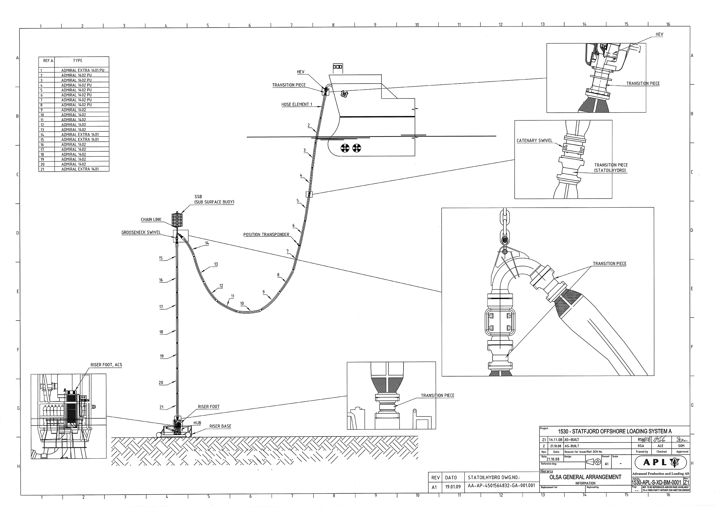
lastebøyer ulike alternativ, illustrasjon, engelsk,
UKOLS with components.

Norwegian companies Ugland Engineering and Kongsberg had collaborated with Statoil since 1979 to develop a simpler and cheaper loading system for use on Statfjord. The key elements in the design philosophy were:

  • use of flexible risers
  • permanent installation on the field
  • use of dynamically positioned shuttle tankers
  • simple installation and connection.

After a few years, the latticework column on the A loading buoy proved to have suffered extensive cracking, and it had to be removed to land for repairs. That provided a golden opportunity to adopt the new-generation solution, which had now been dubbed the Ugland-Kongsberg offshore loading system (UKOLS).

System components are:

    1. riser base on the seabed
    2. vertical flexible riser
    3. subsea swivel
    4. subsea buoyancy tank
    5. catenary riser.

When the system was not in use, the catenary riser was laid on the seabed, attached to a small surface buoy. A shuttle tanker arriving on the field picked up the buoy, hauled in the riser and attached the latter to a loading system in the bows. Once loading was completed, the riser simply had to be disconnected and lowered back into the sea with the attached buoy.

STL – building on experience

US oil company Kerr-McGee approached Statoil in the early 1980s to ask whether a loading system existed which could operate in worse weather than existing solutions. It knew Statoil had expertise in this area.

Departmental head Kåre Breivik, ever bold and optimistic, replied that the company indeed had such a solution. He did not possess a finished product at the time, but drew on his contacts and opportunities in order to develop what was eventually called the submerged turret loading (STL) system. Presented for the first time in 1992, this solution was an eye-opener. Tests at Marintek in Trondheim showed that it could permit loading in maximum wave heights of 30 metres, compared with the 10 metres which were the limit for existing systems.

In this solution, the loading hose was connected to a conical buoy ­– a turret, in technical terms – which could be pulled into a compartment in the base of the ship’s hull. Mooring lines for the vessel were also attached to the buoy, so that it could weathervane freely and always remain bows-on to the wind and waves.

The first application for the STL system was on Fulmar in the UK North Sea during 1993. On the NCS, this solution has been chosen for the Heidrun platform in the Norwegian Sea.

Sources:
Smith, Ron. 14th Lillehammer Energy Claims Conference, Lillehammer, 25 February 2009.
Mork, Kjell. OTC 5747, Ugland Engineering A/S. Offshore Technology Conference, Houston, 1988.
Lindøe, John Ove. From Sea to Shore . Stavanger, 2009.

Published July 9, 2018   •   Updated January 3, 2020
© Norsk Oljemuseum
close Close

Leave a Reply

Your email address will not be published. Required fields are marked *