By accessing www.kulturminne-statfjord.no, you declare that you understand and accept the following terms and conditions: This web site, including its contents, the selection and the organisation of the content on each page or collection of pages, is the sole and exclusive property of the Norwegian Petroleum Museum and Statoil. We reserve all rights to this material.
You may only store extracts from the web site on your personal computer and print out copies of these extracts for your personal, non-commercial use. You may also use and distribute limited and necessary extracts from the web site for facilitating links to its pages or to internet search services.
All other use, such as reproduction, translation, editing, arrangement, and all other changes, distribution or storage of this web site or its content in any form and with any tool, wholly or partly, is prohibited without the written consent in advance of the Norwegian Petroleum Museum and Statoil.
The information presented on this web site will not always be accurate, updated or applicable to the circumstances of a particular event/case. The Norwegian Petroleum Museum and Statoil can accept no liability of any kind for inaccuracies or omissions in the information found on this site.
Neither the Norwegian Petroleum Museum nor Statoil accepts any liability for direct, indirect, special, substantial or other loss or damage of any kind whatsoever which might follow from accessing or using this web site or its content.
The Norwegian Petroleum Museum and Statoil accept no liability for the content of any web sites you may access through this website. That includes web sites accessed via hyperlinks provided on the website. We accordingly accept no liability for the content of any other web site.
Should any errors or inaccuracies be discovered, we would be grateful if you could report these to post@norskolje.museum.no .
Related media:
navigate_beforenavigate_next
Published August 9, 2019 • Updated November 19, 2019
person
By Harald Tønnesen and Finn Harald Sandberg, Norwegian Petroleum Museum
The Statfjord A platform stands in 145.3 metres of water in the centre of the field. It ranks as the fourth Condeep to be built. This installation comprises a concrete gravity base structure (GBS) supporting a steel topside . The topside was fabricated by Aker Stord in western Norway and was mated with the GBS in the adjacent Digernessund sound before tow-out to the field.
— Statfjord A platform with the two flotels Nortrym and Polymarines. Photo: Statoil on behalf of the Statfjord Group.
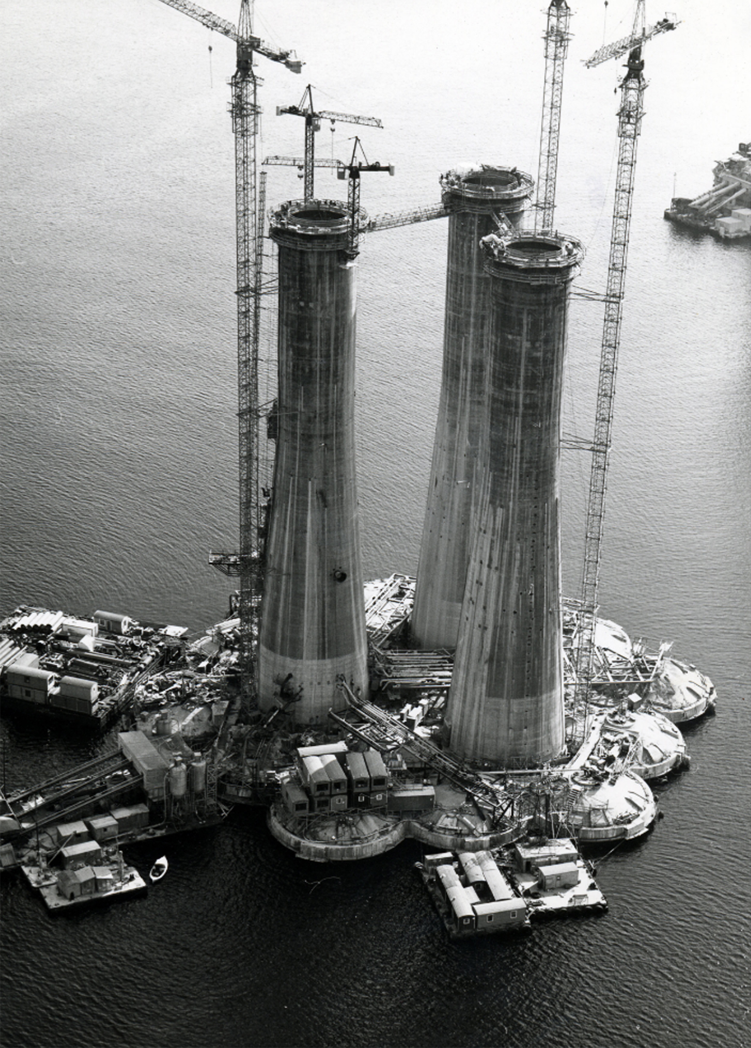
støping av a-en,De tre skaftene er ferdig støpt. Sementblandeverket kan ses i venstre hjørne. Foto: Norwegian Contractors//Norsk Oljemuseum
Built by Norwegian Contractors at Hinnavågen in Stavanger, the GBS comprises 19 cells arranged in a concentric formation. Most of these are used for oil storage. Three have been extended upwards as shafts to carry the topside. The platform, which measures 254 metres in height from the seabed to the top of the drilling derrick, was towed to the field in 1977 and came on stream in November 1979.
Oil was exported via a loading buoy located a few hundred metres away. The original articulated loading platform (ALP) was later replaced by a specially developed Ugland-Kongsberg offshore loading system (Ukols).
Drilling rig
The rig comprises a derrick, modules for such functions as mud mixing, and pipe storage. Wells are drilled through two of the concrete shafts supporting the topside. A total of 42 slots are provided. Both production and gas/water injection wells have been drilled, with an average depth of 2 500-2 800 metres. The derrick stands on skids which allow it to be positioned over the various wells with the aid of hydraulic jacks.
Oppkobling og ferdigstilling,
Statfjord A,
Statfjord A,
Topside
The topside measures 86.2 metres long by 83.6 wide, providing a surface area of 5 000 square metres and total deck space of 21 000 square metres. Total height to the helideck is 43.2 metres, while the base is 28 metres above the sea at its lowest point.
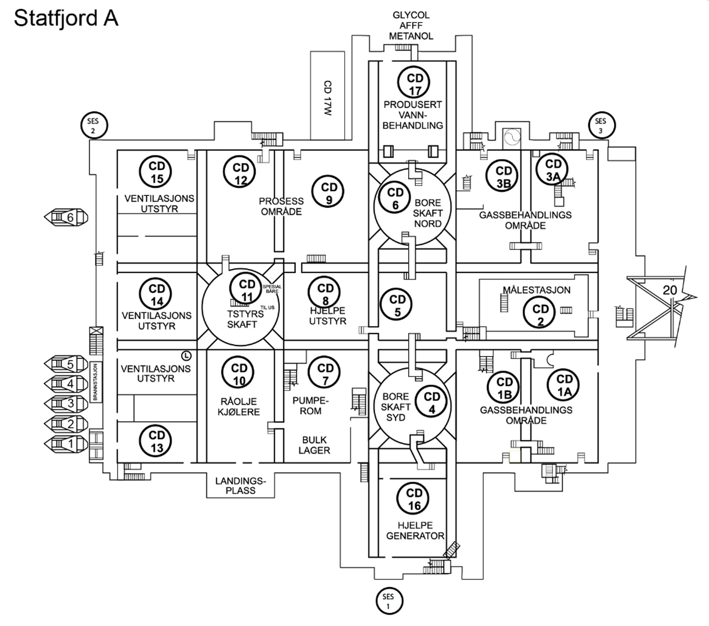
Cellar deck
Statfjord A,Kjellerdekk
The lowest of the steel decks, the cellar deck is built into the module support frame (MSF) which carries the rest of the superstructure. Divided into individual sections with double bulkheads, it forms an integrated steel structure. The flare boom extends for 116 metres at an angle of 45 degrees from its eastern end to burn off all associated gas for brief periods.
Module deck
Statfjord A,Moduldekk
Located above the cellar deck, this has acquired its name because it is partly composed of prefabricated modules. The south-western corner, with the M11, M12, M14,M15, M17 and M18 units, forms part of the cellar deck’s integrated steel structure.
Upper module deck
With the exception of UM7, this deck is built up entirely of modules and lies immediately above the module deck. UM7, which is part of the drilling module, has been constructed as an integrated steel structure together with the cellar deck and the south-western part of the module deck.
Statfjord A,Upper module deck
Living quarters
Bygging av A-dekket,The living quarter of Statfjord A is ready to be connected with the topside. Photo: Johan Brun/Norwegian Petroleum Museum
The living quarters provide 100 cabins. These were originally two-berth but converted for single occupancy in 2000-2003. The six-storey structure comprises three modules. A partial seventh floor is provided by the helideck, radio shack and helicopter fuel tanks. The marine control centre was positioned there in the early years, but later moved to Bergen. In addition to the cabins come a canteen and recreation rooms. A lift and internal staircase connect the floors, while external staircases serve as emergency exits. The illustration shows the layout of a typical cabin in the living quarters.
Weather deck
The tops of the uppermost modules form the weather deck. This area is used for storage and for loading/discharging cargo by the large platform cranes.
Concrete GBS
støping av a-en,Betongunderstellet til Statfjord A under bygging. Foto: Ukjent/Norsk Oljemuseum
The lower section of the GBS comprises 19 concrete cells. Sixteen of these are used for storage, while three extend upwards to form the shafts supporting the topside.
Storage cells
With an internal diameter of 19 metres and a height of 67 metres, the storage cells are individual concrete cylinders which each have a capacity of 80 000 barrels.
Fifteen of the cells are used to store crude oil, and can collectively hold about 1.2 million barrels. Cell 6 is equipped with an internal cylindrical tank to store up to 21 750 barrels of diesel oil. The annulus between the internal cylinder and the cell wall provides 63 500 barrels of storage space for the oil-water emulsion (sludge) which forms during platform operation. All 16 of the cells are partly filled with sand ballast covered by a concrete lid. They are kept filled with liquid at all times. When oil is exported, the cells take in water to maintain their liquid content.
Utility shaft
Statfjord A,Inside one of the utility shafts. Photo: Aker/Norwegian Petroleum Museum
One of the three shafts supporting the topside, this contains a series of decks carrying pumps for fire, ballast and sea water, ballast water tanks and pumps for crude oil loading.
Drilling shafts
These are completely filled with conductor tubing for a total of 16 wells in each shaft. The illustration shows the distribution between production and water/gas injection wells.
Statfjord A,Statfjord A. Photo: Marit Hommedal/Equinor


 støping av a-en,


 Statfjord A,
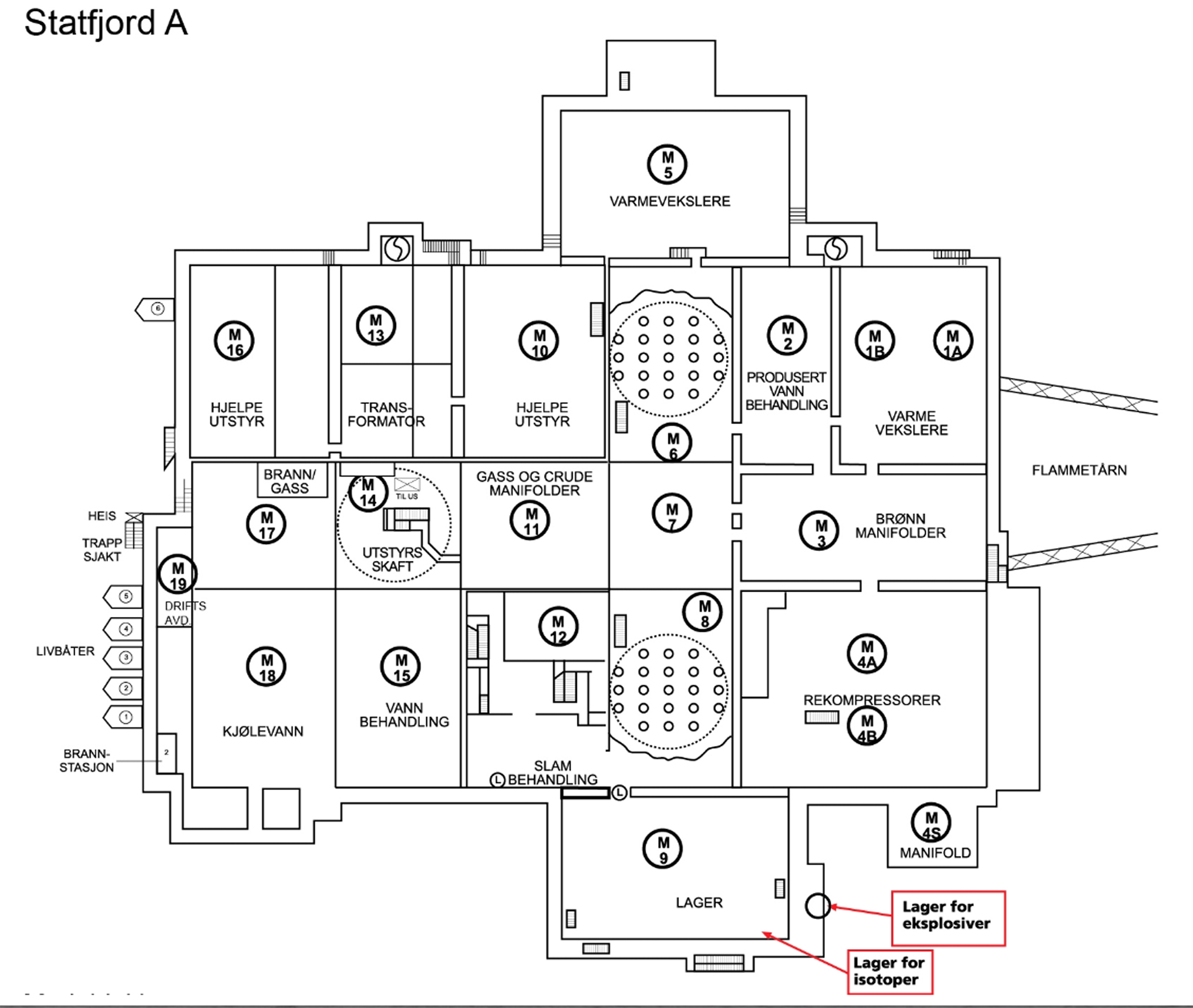 Statfjord A,
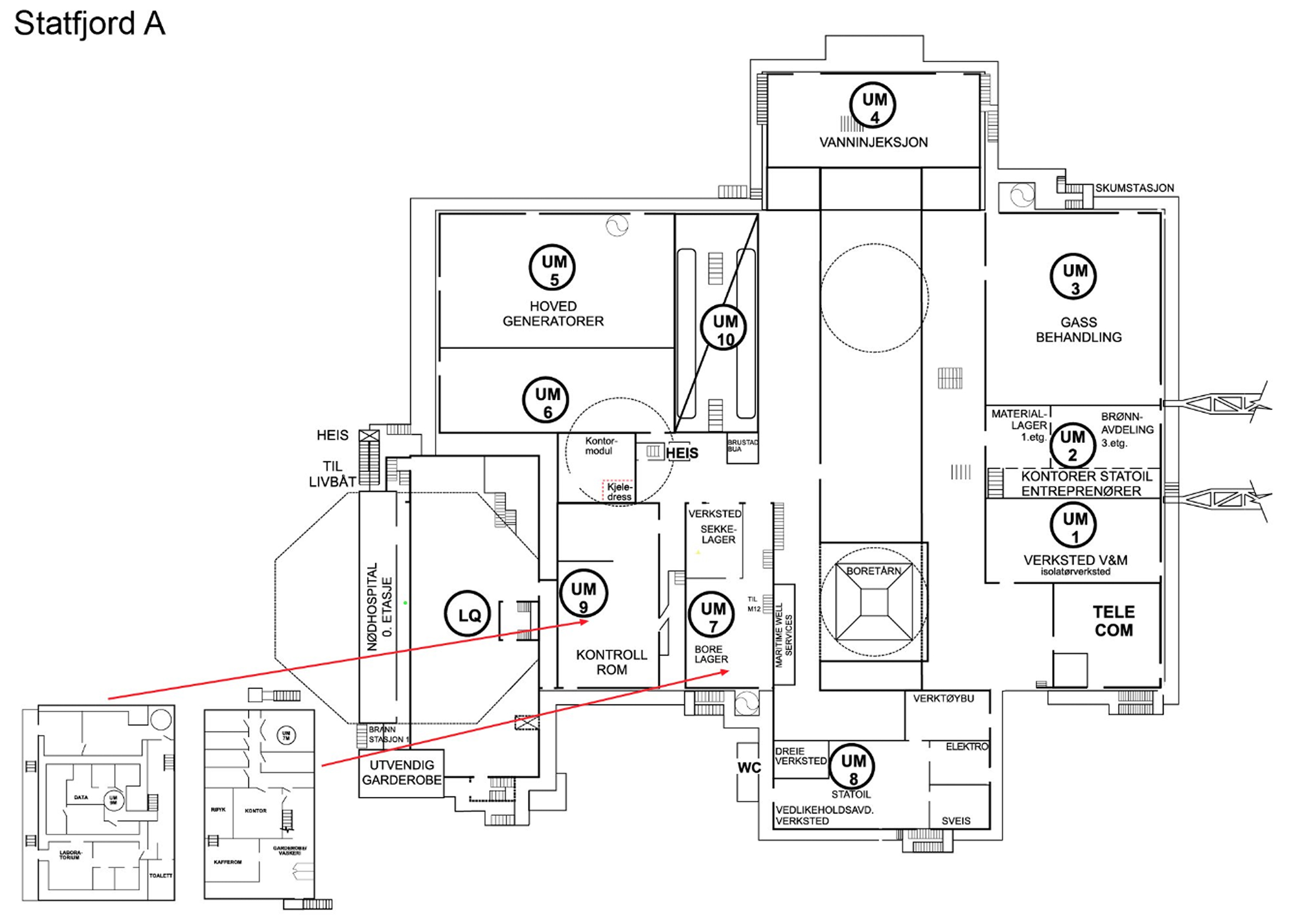 Statfjord A,
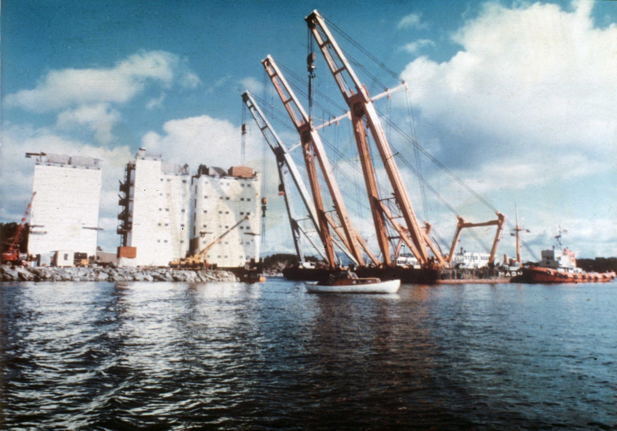 Bygging av A-dekket,
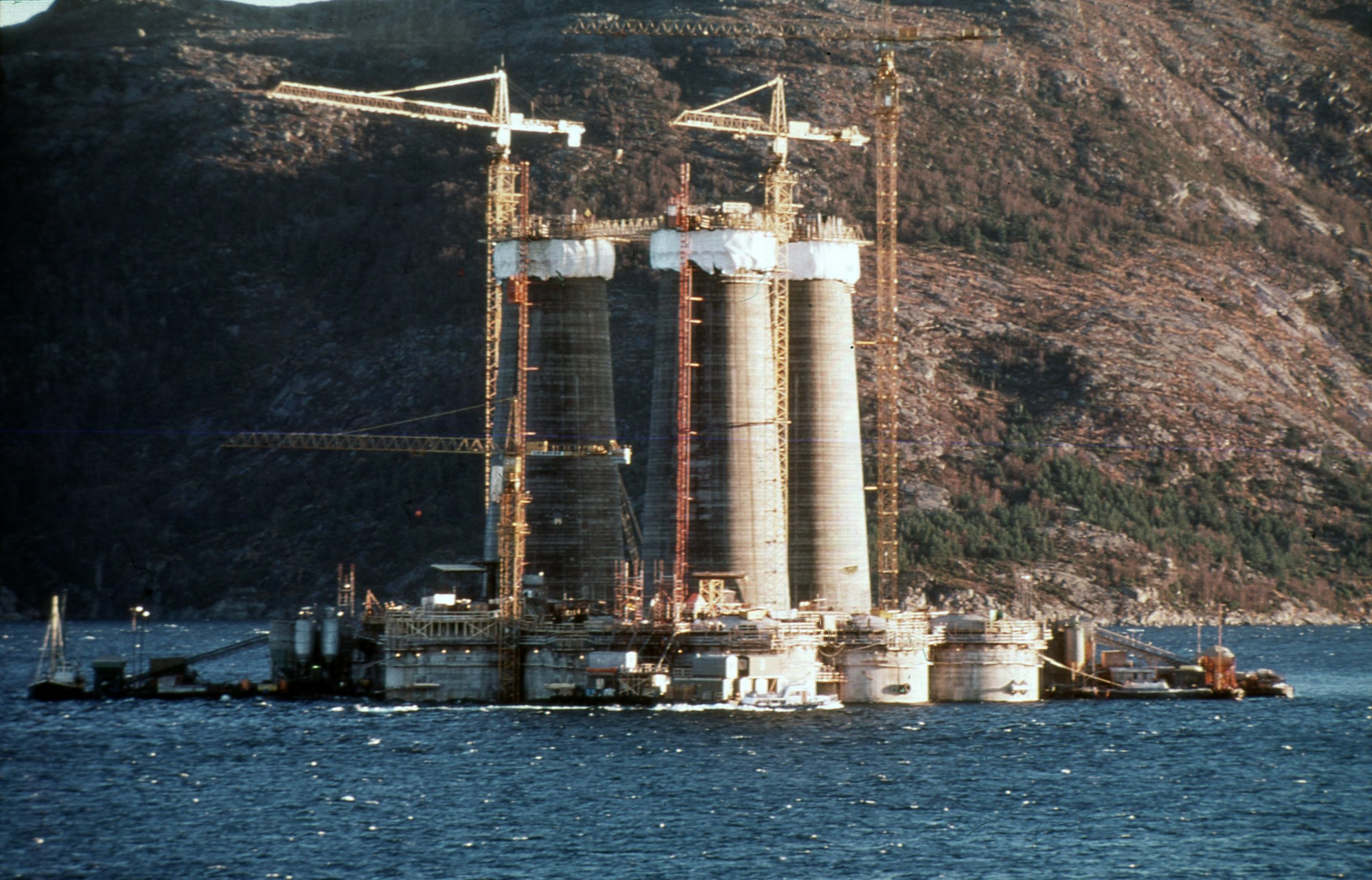 støping av a-en,
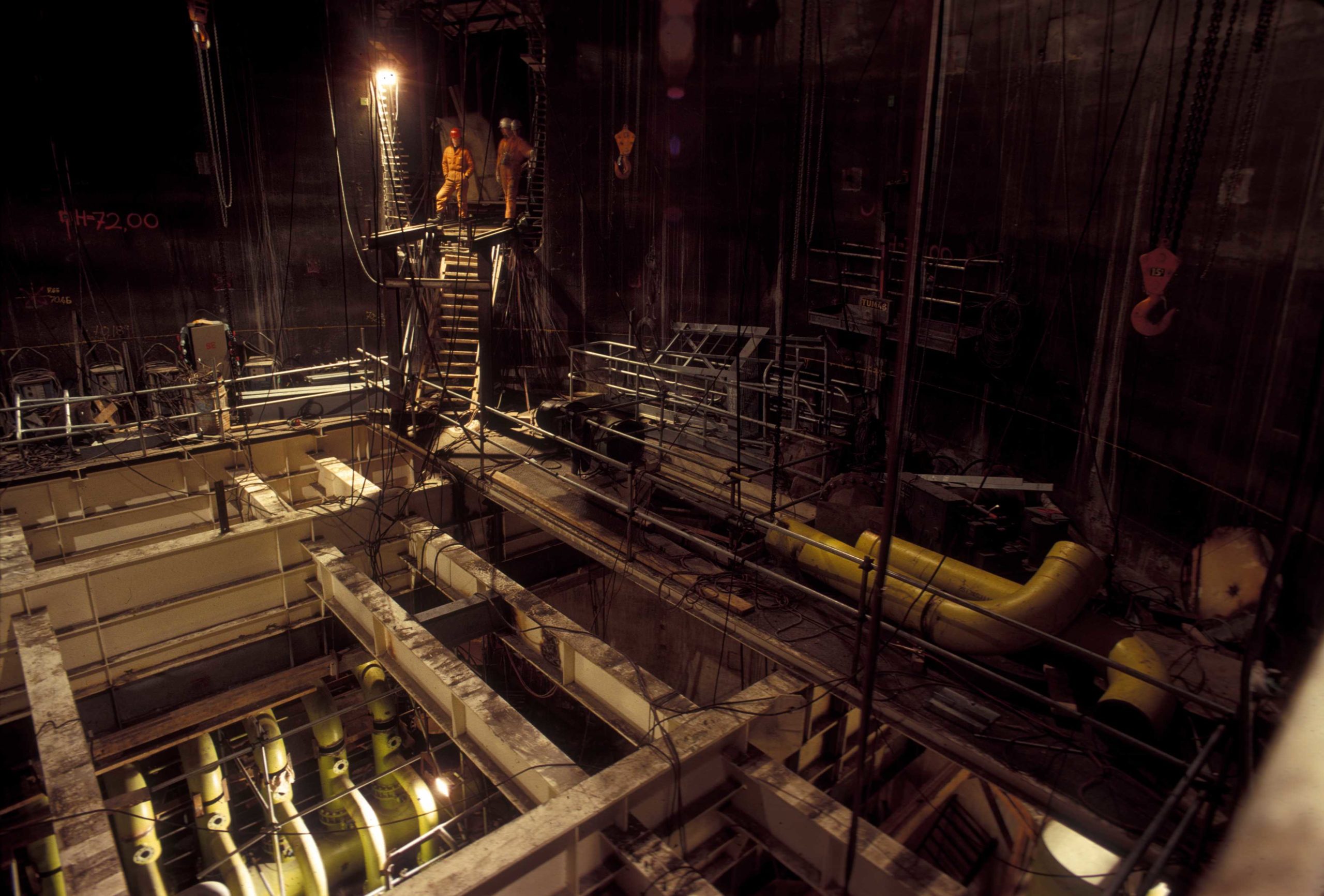 Statfjord A,
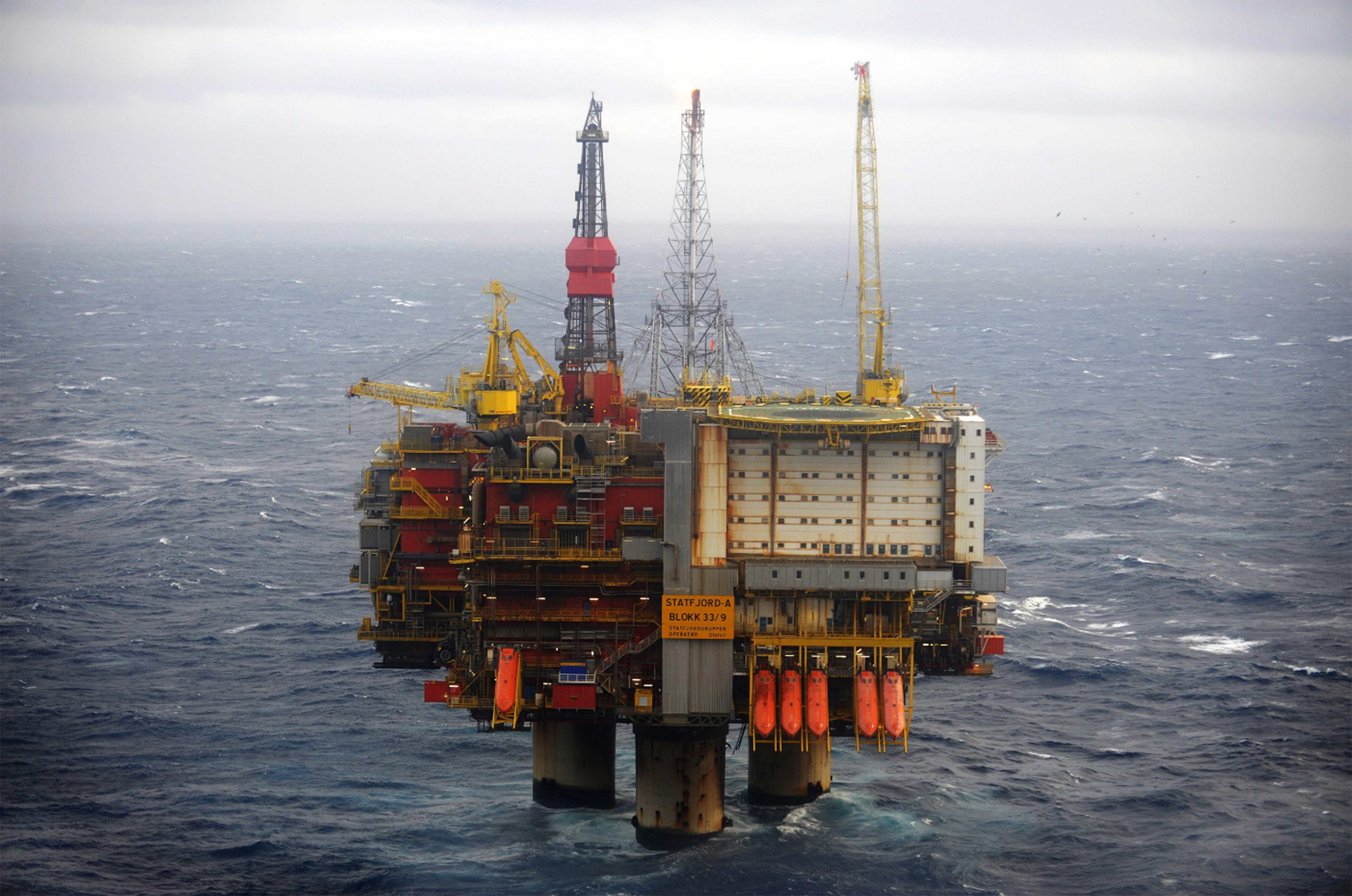 Statfjord A,